Electronic lock and electric executing device thereof
A technology of electric execution and equipment, which is applied to building locks, non-mechanical transmission-operated locks, buildings, etc., can solve the problems of large power consumption and achieve the effects of reduced loss, high safety and stability, and low energy loss
Active Publication Date: 2017-09-15
北京中兴创远科技有限公司
View PDF4 Cites 1 Cited by
- Summary
- Abstract
- Description
- Claims
- Application Information
AI Technical Summary
Problems solved by technology
[0005] In the prior art, the motor rotation of the electric actuator uses the principle of a screw or a stepping drive block to realize the forward and backward movement of the lock tongue, which consumes a lot of power
Method used
View moreImage
Smart ImageViewing Examples

Examples
Embodiment 2
[0081] The embodiment of the present invention also provides an electronic lock, including the electric actuator described in the first embodiment.
[0082] In this embodiment, by using the electric actuator described in Embodiment 1, the energy loss can be effectively reduced, and the switching speed between the locked state and the unlocked state is fast, and the safety and stability are high.
Login to View More PUM
 Abstract
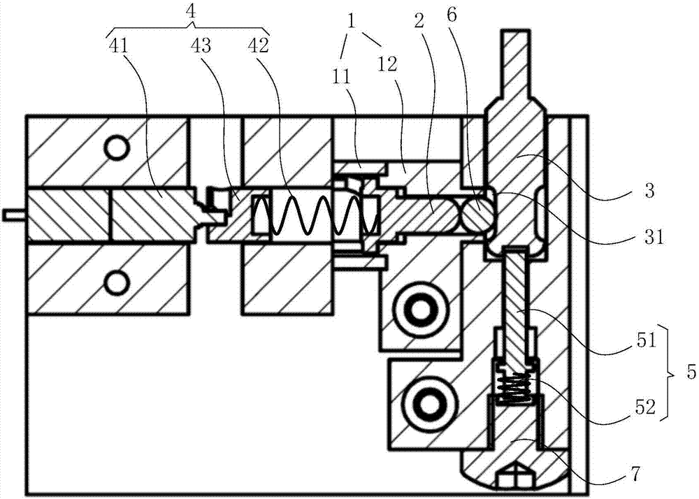
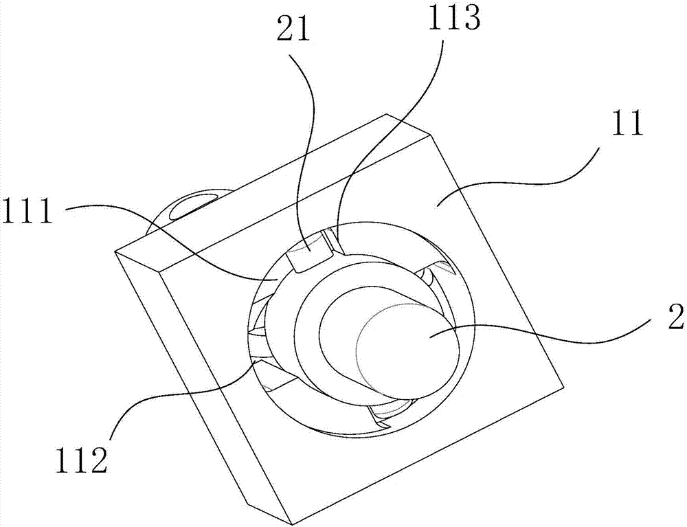
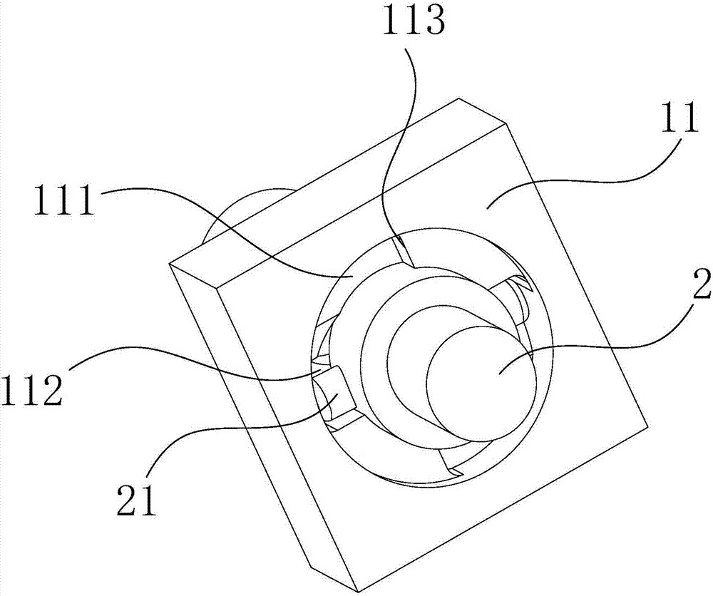
The invention discloses an electronic lock and an electric executing device of the electronic lock and relates to the technical field of mechanical devices. The electric executing device of the electronic lock comprises a lock sleeve, a first ejector pin, a lock rod, a drive device and a springback mechanism. The lock sleeve and the first ejector pin are arranged on one side of the lock rod. The first ejector pin is located in the lock sleeve. The inner wall of the lock sleeve is provided with sliding ways. Each sliding way and the axis of the first ejector pin forms an included angle. The side wall of the iron rod is provided with a lock groove. One end of the first ejector pin is connected with the drive device. The drive device is used for driving the first ejector pin to rotate along the sliding ways of the lock sleeve so that the other end of the first ejector pin can be far away from the lock groove or is close to and clamps the lock groove. One end of the lock rod is connected with the springback mechanism. The springback mechanism is used for exerting pressure on the lock rod in the axial direction of the lock rod. In this way, the electronic lock and the electric executing device of the electronic lock can greatly reduce the loss and is high in safety and stability.
Description
technical field [0001] The invention relates to the technical field of mechanical equipment, in particular to an electronic lock and its electric actuator. Background technique [0002] In the current era of intelligent electronic products, intelligent hardware products have gradually entered various fields of life. Various electronic locks such as home electronic door locks, electronic padlocks, luggage electronic locks, etc. are widely used, which opens the experience of a new generation of intelligent life. [0003] At present, the electric actuator is the core module of the electronic lock, and the electric actuator is mainly used to realize intelligent unlocking and locking. The electric actuators in the prior art all use geared motors to drive the deadbolt to move back and forth to realize locking and disengagement of the lock bar. [0004] In the process of implementing the embodiments of the present invention, the inventors found that the prior art has at least the ...
Claims
Login to View More Application Information
Patent Timeline
 IPC IPC(8): E05B47/00E05B15/10E05B15/14E05B15/00
CPCE05B15/00E05B15/10E05B15/14E05B47/0012
Inventor 郭小敏
Owner 北京中兴创远科技有限公司
Features
- R&D
- Intellectual Property
- Life Sciences
- Materials
- Tech Scout
- Unparalleled Data Quality
- Higher Quality Content
- 60% Fewer Hallucinations
Learn More Browse by: Latest US Patents, China's latest patents, Technical Efficacy Thesaurus, Application Domain, Technology Topic, Popular Technical Reports.
© 2025 PatSnap. All rights reserved.Legal|Privacy policy|Modern Slavery Act Transparency Statement|Sitemap|About US| Contact US: help@patsnap.com