Stamping necking mold for pipe fittings

A technology for pipe fittings and molds, used in forming tools, manufacturing tools, metal processing equipment, etc., can solve problems such as easy deformation of the working stroke, and achieve the effect of shortening the working stroke, reducing the possibility of deformation, and increasing the supported length

Inactive Publication Date: 2017-08-29
柳州市御朗机械制造有限公司
View PDF7 Cites 3 Cited by
  • Summary
  • Abstract
  • Description
  • Claims
  • Application Information

AI Technical Summary

Problems solved by technology

[0003] The purpose of the present invention is to provide a die for punching and shrinking pipe fittings, which can solve the problems of the existing shrinking dies for pipe fittings, which are easy to deform when shrinking longer pipe fittings and have a larger working stroke

Method used


Image

  • Stamping necking mold for pipe fittings
  • Stamping necking mold for pipe fittings
  • Stamping necking mold for pipe fittings

Examples


Embodiment Construction

[0014] The present invention will be described in further detail below in conjunction with accompanying drawing embodiment:

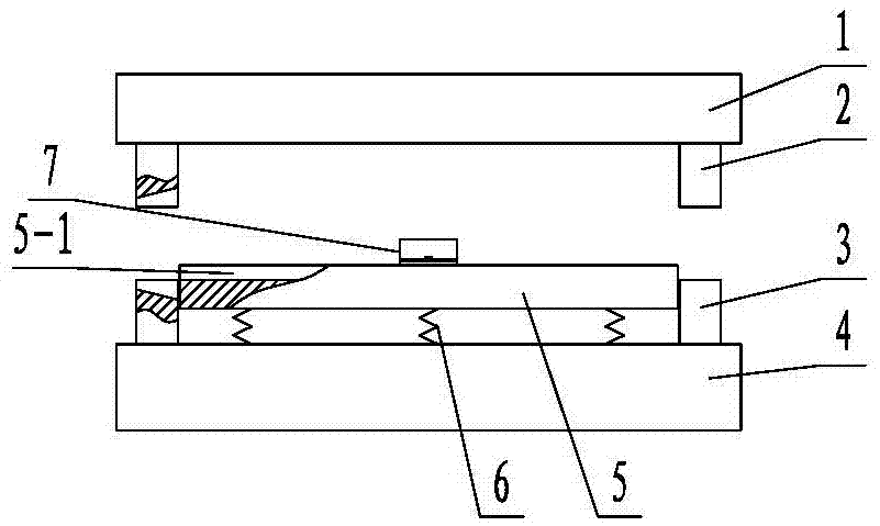
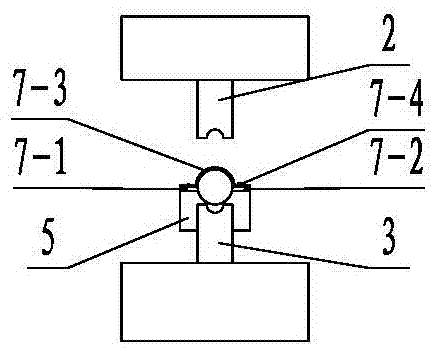
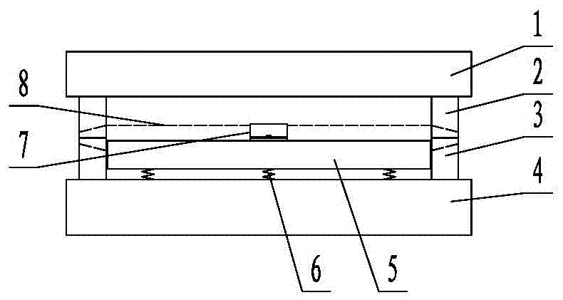
[0015] figure 1 with figure 2 The pipe fitting stamping die shown mainly includes an upper template 1, an upper die 2, a lower die 3, a lower die base 4, a support block 5, a spring 6 and a jacket 7, and two opposite die bases are fixed on the lower die base 4. The lower die 3 provided is fixed with two upper dies 2 corresponding to the two lower dies 3 on the upper template 1, and the corresponding upper die 2 and the lower die 3 are enclosed to form a shrinkage cavity; Between the two lower dies 3, a support block 5 supported by a plurality of springs 6 on the top of the lower die base 4 is provided. There are stops, 5-1, for horizontally placing pipe fittings 8, see image 3 , the two ends of the limit groove 5-1 are respectively set towards the lower die 3, the cross-sectional profile of the limit groove 5-1 is a inferior arc matched with the pi...


PUM


Abstract

The invention discloses a stamping necking mold for pipe fittings and relates to the technical field of stamping molds. The stamping necking mold comprises two lower female mold bodies which are oppositely fixed to a lower mold seat. A support block is arranged between the two lower female mold bodies. The support block is supported above the lower mold seat through multiple springs. A limiting groove for horizontally containing the pipe fittings is formed in the upper end face of the support block. Two upper female mold bodies corresponding to the lower female mold bodies are fixedly arranged on an upper mold plate. A necking mold cavity is defined by the upper female mold bodies and the lower female mold bodies. The stamping necking mold for the pipe fittings solves the problems that by means of an existing necking mold for the pipe fittings, necked openings of overlong pipe fittings deform easily, and the working stroke is large.

Description

technical field [0001] The invention relates to the technical field of punching dies, in particular to a punching die for pipe fittings. Background technique [0002] Pipe fitting necking is a molding process that reduces the diameter of the end of the tube blank. In the past, the upper necking die was used to shrink the pipe fittings, and the lower end of the pipe fittings was fixed on the press table, and the pipe fittings were placed in an upright state. Drive the upper necking die down, when the pipe fittings are in contact with the upper die, under strong pressure, the upper end of the pipe fittings is squeezed into the necking cavity of the upper necking die to achieve shrinking, but it can only Necking one end of the pipe fitting is less efficient. An existing stamping die with necking at both ends includes an upper mold, a chuck and a lower mold. The upper mold and the lower mold are respectively provided with corresponding shrinking cavities, and the chuck is place...

Claims


Application Information

Patent Timeline
Patent Type & Authority Applications(China)
IPC IPC(8): B21D37/10B21D41/04B21D43/00
CPCB21D37/10B21D41/04B21D43/003
Inventor 梁宇松
Owner 柳州市御朗机械制造有限公司
Why Eureka
Try Eureka