Upper layer high-pressure negative-pressure separated exploiting device

A high-pressure negative pressure, set-up technology, applied in wellbore/well valve device, production fluid, earth-moving drilling and other directions, can solve the problems of low negative pressure, small size of fluid channel in low pressure area, complex structure, etc.

Pending Publication Date: 2017-09-15
CNPC BOHAI DRILLING ENG
View PDF12 Cites 1 Cited by
  • Summary
  • Abstract
  • Description
  • Claims
  • Application Information

AI Technical Summary

Problems solved by technology

However, the existing equipment has the problem of complex structure, small negative pressure, and small fluid channel size in the low-pressure area, which can adapt to the small interlayer pressure difference (mostly wi

Method used


Image

  • Upper layer high-pressure negative-pressure separated exploiting device
  • Upper layer high-pressure negative-pressure separated exploiting device
  • Upper layer high-pressure negative-pressure separated exploiting device

Examples


Embodiment Construction

[0020] The present invention will be further described below in conjunction with the accompanying drawings and specific embodiments, but the following embodiments in no way limit the present invention.

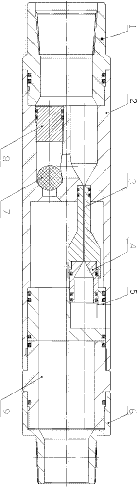
[0021] Such as figure 1 As shown, the upper-layer high-pressure negative pressure split mining device includes an upper joint 1, a main body 2, a connecting cylinder 9, and a lower joint 6 that are threaded sequentially from top to bottom; the inner side of the main body 2 is provided with a throat 3, a nozzle 4, and a pressure cap 5 , Ball valve 7 and valve seat 8.

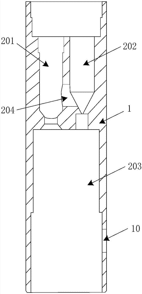
[0022] Such as figure 2 As shown, the main body 2 is a cylindrical structure, and a first eccentric through hole 201 and a second eccentric through hole 202 are respectively opened from the top surface of the main body 2 along the axial direction, and a central through hole 203 is opened from the bottom surface of the main body 2; The eccentric through hole 201 and the second eccentric through hole 202 communi...


PUM


Abstract

The invention discloses an upper layer high-pressure negative-pressure separated exploiting device. The upper layer high-pressure negative-pressure separated exploiting device comprises a main body, a valve seat, a ball valve, a throat pipe and a pressing cap, wherein a first eccentric through hole and a second eccentric through hole are formed in the top surface of the main body, a central through hole is formed in the bottom surface of the main body, and the first eccentric through hole and the second eccentric through hole communicate with the central through hole; the valve seat and the ball vale are arranged at the end of the top end of the first eccentric through hole and the communicating part between the first eccentric through hole and the central through hole correspondingly, a communicating hole formed in the portion between the first eccentric through hole and the second eccentric through hole is formed above the ball valve; the throat pipe is installed at the bottom of the second eccentric through hole in an inserted mode, the inner diameter of the bottom end of the throat pipe is increased, and the bottom end of the throat pipe is provided with a spraying nozzle, and thus a central hole channel of the throat pipe, the second eccentric trough hole and a central hole channel are connected sequentially; the pressing cap is arranged on the inner wall of the lower side of the main body, a third eccentric through hole and a fourth eccentric through hole are formed in the top surface of the pressing cap, and the fourth eccentric through hole communicates with an overflowing hole which is formed in the side wall of the lower side of the main body. According to the upper layer high-pressure negative-pressure separated exploiting device, the through capability of fluid in the low pressure area is maximally improved, the application range of interlayer pressure differences of tools is enlarged, and the exploiting efficiency is greatly improved.

Description

technical field [0001] The invention relates to the technical field of oilfield development, in particular to an upper-layer high-pressure negative-pressure separate production device. Background technique [0002] With the passage of oilfield development time, most of the oil wells have entered the stage of high recovery, and the difficulty of improving the recovery rate is increasing year by year, and the difficulty of measures is increasing. During the oilfield development process in recent years, single-layer production or multi-layer combined production is the main method. After multi-layer commingled production, the production of some oil wells did not increase as expected, and there were even extreme cases of negative production growth. Usually, the interlayer pressure difference between the original mining layer and the newly opened layer is as high as 5MPa, and the interlayer contradiction is very prominent, resulting in the phenomenon of backflow from the high pre...

Claims


Application Information

Patent Timeline
IPC IPC(8): E21B43/14E21B34/08
CPCE21B34/08E21B43/14
Inventor 杜成良孙红岗高硕凌龙任永宏胡鹏陶婧赵建鹏凌云王鹏陈海波高丽萍王军
Owner CNPC BOHAI DRILLING ENG
Why Eureka
Try Eureka