Retrofit lamp

A light source module and heat sink technology, which is applied in the direction of lighting devices, the use of semiconductor lamps, and components of lighting devices, can solve the problems of high component and installation costs, reduce insulation distances, etc., and achieve small installation costs and long insulation distances , Improve the effect of ESD compatibility

Inactive Publication Date: 2017-09-15
LEDVANCE GMBH
View PDF7 Cites 0 Cited by
  • Summary
  • Abstract
  • Description
  • Claims
  • Application Information

AI Technical Summary

Problems solved by technology

The disadvantage here is that screw connections lead to high component and installation costs and can also reduce insulation distances

Method used


Image

  • Retrofit lamp
  • Retrofit lamp
  • Retrofit lamp

Examples


Embodiment Construction

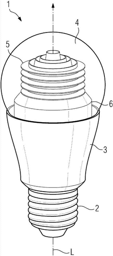
[0039] figure 1 A perspective view of a retrofit lamp 1 for replacing conventional incandescent lamps is shown. A retrofit lamp 1 with a longitudinal axis L has an Edison base 2 (for example of type E27) on its rear end. The Edison base 2 is connected forwardly to a housing 3 , for example made of plastic, which supports or holds a light-transmitting bulb 4 at the front. The bulb 4 houses a light-transmitting optical element (“lens” 5 ) as well as a ring 6 which supports or fixes the lens 5 . The bulb 4 can be transparent or diffuse.

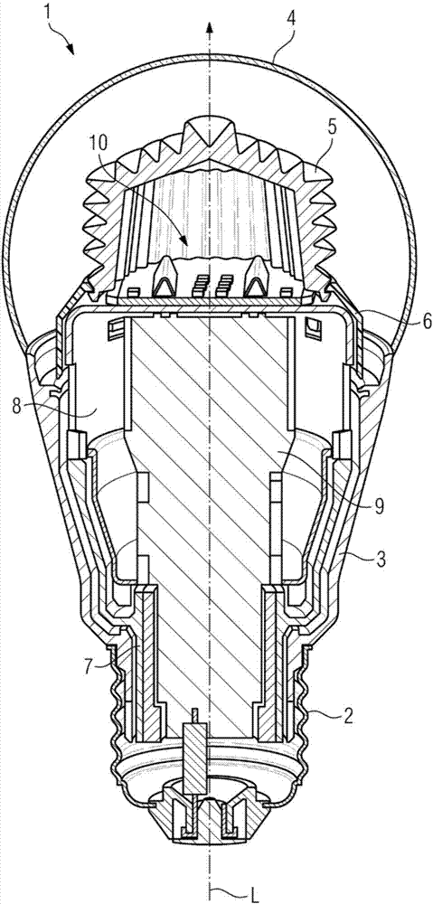
[0040] figure 2 The retrofit lamp 1 is shown in oblique sectional view. The housing 3 laterally surrounds drive housings 7, 8 in which the drive 9 is placed. The drive housings 7 , 8 have a base-side, cup-shaped lower part 7 and an upper, cup-shaped cover, which serves as a heat sink 8 . The lower part 7 can consist of metal or plastic. The heat sink 8 consists here of metal, for example of aluminum.

[0041] The LED module 10 rests on ...


PUM


Abstract

A retrofit lamp (1) comprises a heat sink (8), a light source module (10) with a circuit board (11), whose rear side lies two-dimensionally on the heat sink (8) and at the front side of which at least one semiconductor light source (12) is arranged, and a ring (6) partially covering the front side of the light source module (10), wherein the ring (6) presses the light source module (10) onto the heat sink (8). A method serves for producing a retrofit lamp (1), wherein the rear side of the circuit board (11) of the light source module (10) is laid on the heat sink (8) and the ring (6) is put on the retrofit lamp (1) from the front such that it presses the light source module (10) onto the heat sink (8). The invention is particularly applicable to LED retrofit lamps for replacing conventional light bulbs or halogen lamps.

Description

technical field [0001] The invention relates to a retrofit lamp having a heat sink, a light source module with a circuit board, the circuit board is placed on the heat sink with its rear side flat and at least one semiconductor light source is arranged in front of the circuit board. The invention is particularly applicable to LED retrofit lamps to replace conventional incandescent or halogen lamps. Background technique [0002] LED retrofit lamps of a related type are known in which, in order to produce an efficient heat transfer from the light source module to the heat sink, there is a thermally conductive glue, thermally conductive film or thermally conductive paste between these two parts. The two parts are continuously pressed against each other by means of a screw connection. The disadvantage here is that screw connections lead to high component and installation costs and can also reduce insulation distances. Contents of the invention [0003] The object of the pres...

Claims


Application Information

Patent Timeline
Patent Type & Authority Applications(China)
IPC IPC(8): F21K9/23F21V19/00F21V29/503F21Y115/10
CPCF21V19/0015F21V29/503F21K9/90F21V5/04F21V17/16F21V19/004F21V29/70F21V29/89F21K9/232F21K9/235F21K9/237F21K9/69F21Y2105/10F21Y2115/10F21V5/10Y02B20/30F21V19/003F21K9/238
Inventor 兰伯特·弗赖克劳斯·埃克特伊莎贝尔·斯克劳兹
Owner LEDVANCE GMBH
Why Eureka
Try Eureka