
Navigation lamp

A technology for navigation lights and LED light substrates, applied in the field of navigation lights, can solve the problems of blind spots, low heat dissipation efficiency, waste, etc., and achieve the effects of convenient installation and disassembly, increasing the heat dissipation area, and improving the irradiation effect.

Inactive Publication Date: 2017-09-15
成都鑫晨航空科技有限公司
View PDF0 Cites 0 Cited by
  • Summary
  • Abstract
  • Description
  • Claims
  • Application Information

AI Technical Summary

Problems solved by technology

[0003] Most of the existing aviation lights use LED lights, but the heat dissipation problem of LED lights is also a key issue, which seriously affects the light efficiency and life of LED light sources
For traditional LED lamps, the lampshade used for concentrating light is generally closed. Such a lampshade cannot dissipate heat from the substrate, resulting in low heat dissipation efficiency, resulting in high temperature of the LED light source and power supply, which affects the LED light. Effectiveness and life
[0004] At present, the navigation lights used in airports have poor adjustment angles and there are blind spots, so it is necessary to add a lot of navigation lights
[0005] In order to ensure the effect of lighting, causing unnecessary waste
Moreover, the existing navigation lights for airports lack lightning protection measures, and there are potential safety hazards

Method used


Image

  • Navigation lamp
  • Navigation lamp
  • Navigation lamp

Examples


Embodiment 1

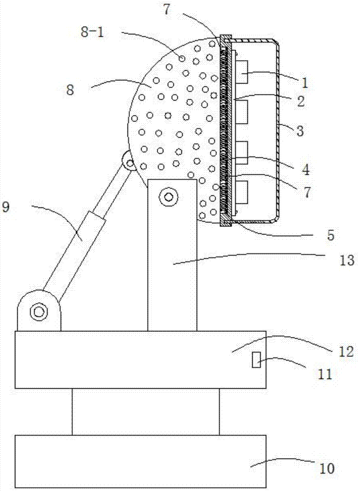
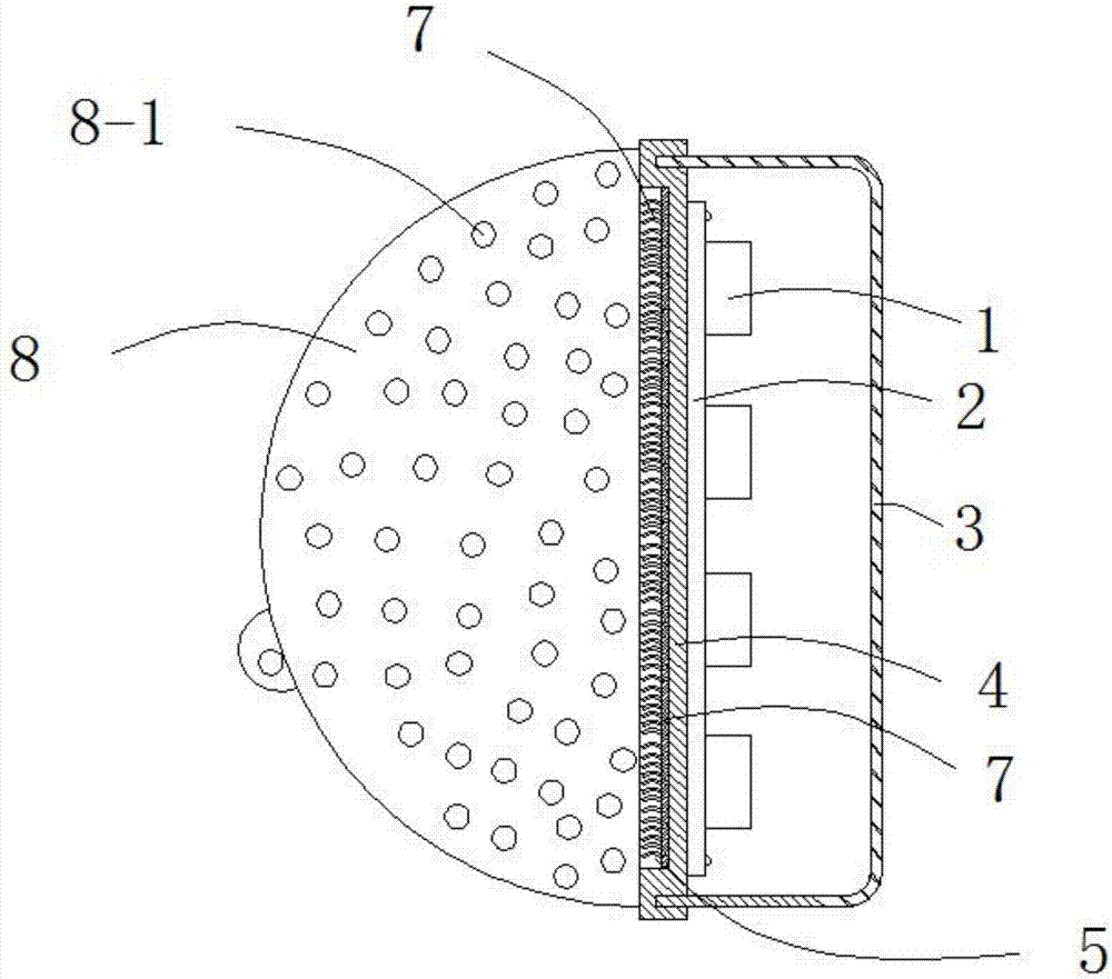
[0023] Such as Figures 1 to 3 As shown, this embodiment provides a navigation light, including an aluminum substrate 4, a transparent shield 3 arranged on the right side of the aluminum substrate 4 and an installation shield 8 arranged on the left side of the aluminum substrate 4, the aluminum substrate 4 and the transparent shield 3 enclosing the LED installation chamber, the LED lamp substrate 2 is arranged on the aluminum substrate 4 in the LED installation chamber. Cooling holes 8-1, a controller casing 12 is arranged under the installation shield 8, a mounting bracket 13 hinged with the installation shield 8 is arranged on the controller casing 12, and a driving installation shield 8 is also arranged on the slewing support 10 The telescopic mechanism 9 selected around the hinge point, the lower end of the controller housing 12 and the slewing support 10 .

[0024] The left side of the aluminum substrate 4 is provided with a heat dissipation groove 5 , and a heat dissipa...

Embodiment 2

[0027] This embodiment is further optimized on the basis of implementation 1, specifically:

[0028] The controller housing 12 is provided with a photosensitive window 11, and the controller housing 12 is provided with a photosensitive controller. The photosensitive window 11 is a convex lens photosensitive window, and a photosensitive device is built in the convex lens photosensitive window.

[0029] The right side edge of the aluminum substrate 4 is provided with a circle of shield embedding grooves 4 - 1 matching the transparent shield 3 .

[0030] The LED lamp heat dissipation assembly 1 includes a disc-shaped bottom plate 1-5 and a shell 1-2 connected to the bottom plate 1-5. Several LED lamp beads 1-1 are integrated on the surface of the bottom plate 1-5, and the shell 1-2 is cylindrical. structure, the outer surface of the shell 1-2 has a number of cooling fins 1-3 evenly distributed on the circumference.

[0031] A heat dissipation through hole 1-2 is provided at the ...


PUM


Abstract

The invention discloses a navigation light, which relates to the field of navigation lights. The invention comprises an aluminum substrate, a transparent shield arranged on the right side of the aluminum substrate, and an installation shield arranged on the left side of the aluminum substrate. The aluminum substrate and the transparent shield form a LED installation cavity, the aluminum substrate in the LED installation cavity is provided with an LED lamp substrate, a number of LED lamp heat dissipation components are arranged on the LED lamp substrate, a number of hollow cooling holes are arranged on the installation shield, and a controller shell is arranged under the installation shield body, the controller housing is provided with a mounting frame hinged with the installation shield, and the slewing support is also provided with a telescopic mechanism that drives the installation shield to rotate around the hinge point, and the lower end of the controller housing is connected to the slewing support. The invention has a simple structure , The angle can be adjusted, and the heat dissipation effect is good.

Description

technical field [0001] The present invention relates to the technical field of navigation lights, and more specifically relates to a navigation light. Background technique [0002] Aircraft refers to a heavier-than-air aircraft that has one or more engines to generate forward thrust or pull, and the fixed wings of the fuselage to generate lift, and fly in the atmosphere. Airplanes are the most common type of fixed-wing aircraft. According to the type of engine it uses, it can be divided into jet aircraft and propeller aircraft. The airplane is one of the most important inventions in the early 20th century, and it is generally recognized that it was invented by the Wright brothers of the Americans. Their flight on December 17, 1903 was recognized by the International Aeronautical Federation (FAI) as "the first controlled sustained powered flight by a heavier-than-air aircraft", and in the same year they founded the "Wright Aircraft Company". Since the invention of airplane...

Claims


Application Information

Patent Timeline
Patent Type & Authority Applications(China)
IPC IPC(8): F21S8/00F21V15/02F21V19/00F21V21/22F21V23/00F21V29/74F21V29/83F21Y115/10
CPCF21S8/00F21V15/02F21V19/001F21V21/22F21V23/003F21V29/74F21V29/83F21Y2115/10
Inventor 石存岭
Owner 成都鑫晨航空科技有限公司
Learn More