Automatic chamfer detection machine

A detection machine and chamfering technology, applied in the direction of measuring devices, instruments, etc., can solve the problems of health hazards for testing personnel, high missed detection rate, slow detection speed, etc.

Active Publication Date: 2017-09-15
KESEN SCI & TECH DONGTAI CO LTD
View PDF6 Cites 1 Cited by
  • Summary
  • Abstract
  • Description
  • Claims
  • Application Information

AI Technical Summary

Problems solved by technology

[0003] The purpose of the present invention is to provide an automatic chamfering detection machine, which can replace manual chamfering detection, and solve the problems of slow detection speed, high missed detection rate and easy damage to the health of the detection personnel in the current human eye detection. The problem of causing harm, and save manpower, the detection process is accurate and reliable, the detection efficiency is high, and the cost is greatly reduced

Method used


Image

  • Automatic chamfer detection machine
  • Automatic chamfer detection machine
  • Automatic chamfer detection machine

Examples


Embodiment 1

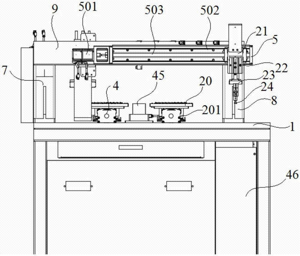
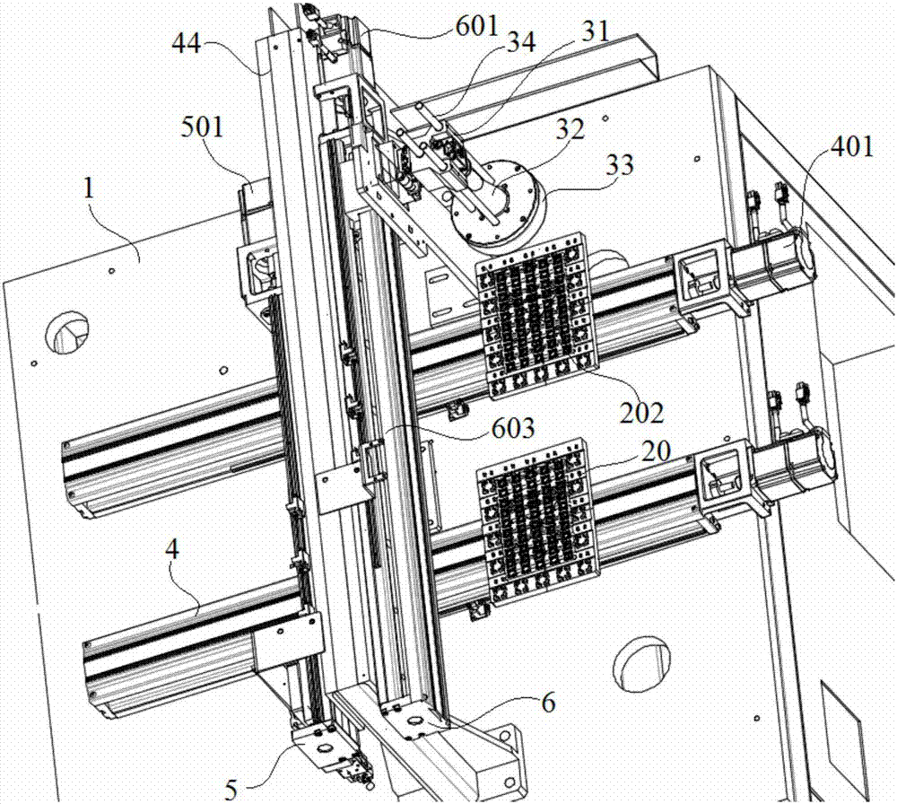
[0024] Embodiment 1: An automatic chamfering detection machine, including a base 1, a support frame 2 installed on the base 1, an X-direction transmission device 4, a front-end Y-direction transmission device 5 and a rear-end Y-direction transmission device 6, the support The frame 2 is composed of a left column 7, a right column 8 and a crossbeam 9. The left column 7 and the right column 8 are respectively fixed on both sides of the upper surface of the base 1, and the crossbeam 9 bridges the tops of the left column 7 and the right column 8. The transmission device 3 is respectively installed on the upper surface of the base 1 and the front and rear sides of the beam 9 of the support frame 2;

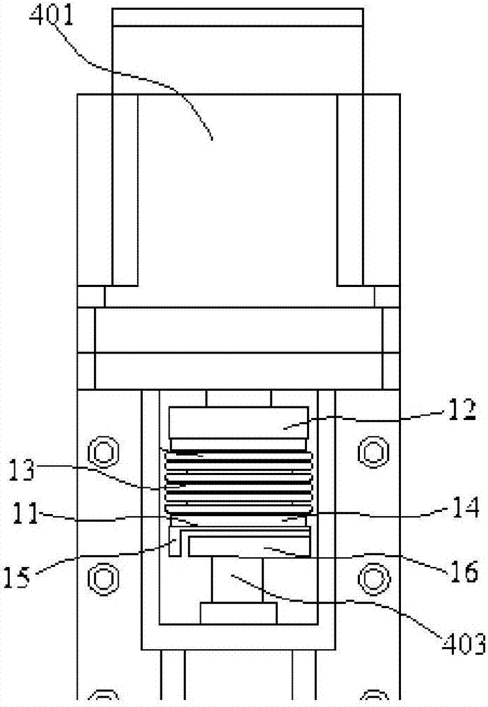
[0025] The X-direction conveying device 4 further includes an X-direction motor 401, two X-direction rails 402, an X-direction screw 403 and an X-direction nut 404. The X-direction motor 401 is installed on the end of the base 1 opposite to the feed inlet, The X-direction screw 403 is ...

Embodiment 2

[0030] Embodiment 2: An automatic chamfering detection machine, including a base 1, a support frame 2 installed on the base 1, an X-direction transmission device 4, a front-end Y-direction transmission device 5 and a rear-end Y-direction transmission device 6, the support The frame 2 is composed of a left column 7, a right column 8 and a crossbeam 9. The left column 7 and the right column 8 are respectively fixed on both sides of the upper surface of the base 1, and the crossbeam 9 bridges the tops of the left column 7 and the right column 8. The transmission device 3 is respectively installed on the upper surface of the base 1 and the front and rear sides of the beam 9 of the support frame 2;

[0031] The X-direction conveying device 4 further includes an X-direction motor 401, two X-direction rails 402, an X-direction screw 403 and an X-direction nut 404. The X-direction motor 401 is installed on the end of the base 1 opposite to the feed inlet, The X-direction screw 403 is ...


PUM


Abstract

The invention discloses an automatic chamfer detection machine. The detection machine comprises a base, a support rack installed on the base, an X-direction transmission device, a front-end Y-direction transmission device and a back-end Y-direction transmission device. The support rack consists of a left column, a right column and a cross beam. The left column and the right column are respectively fixed on two sides of the upper surface of the base. The cross beam is connected to the top ends of the left column and the right column in a crossing manner. The front-end Y-direction transmission device further comprises a front-end Y-direction motor, two front-end Y-direction guide rails, a front-end Y-direction screw rod and a front-end Y-direction nut. The front-end Y-direction motor is installed on one end of a charging side of the support rack. Multiple guidance column through-holes for threading-in of guidance columns are arranged in an adjustment rack. The guidance columns penetrate through the guidance column through holes and are fixedly connected with the upper surface of a light source. A material collecting box used for collecting defective products is arranged in the center of the base. A case where the power supply and the electric control equipment are arranged is arranged under the base. According to the invention, the detection machine is capable of replacing workers to achieve chamfer detection, so all kinds of problems in eye detection are solved; manpower is saved; detection processes are precise and reliable; detection efficiency is high; and cost is greatly reduced.

Description

technical field [0001] The invention relates to an automatic chamfering detection machine and relates to the technical field of detection. Background technique [0002] In the prior art, the detection of the chamfer of the fingerprint ring is mostly through manual measurement, and the detection method is to use strong light to irradiate the parts to be detected, and then detect and distinguish through human eyes. The inspection rate is high, and the strong light is easy to affect the eyesight of the inspectors. Contents of the invention [0003] The purpose of the present invention is to provide an automatic chamfering detection machine, which can replace manual chamfering detection, and solve the problems of slow detection speed, high missed detection rate and easy damage to the health of the detection personnel in the current human eye detection. The problem of causing harm, and saves manpower, the detection process is accurate and reliable, the detection efficiency is ...

Claims


Application Information

Patent Timeline
Patent Type & Authority Applications(China)
IPC IPC(8): G01B21/22
CPCG01B21/22
Inventor 徐金根王海明曹路
Owner KESEN SCI & TECH DONGTAI CO LTD
Why Eureka
Try Eureka