Fiber Bragg Grating Hydrophone and Sound Pressure Sensing System
A fiber grating and hydrophone technology, which is applied in the direction of instruments, measuring ultrasonic/sonic/infrasonic waves, measuring devices, etc., can solve the problems of bulky, easy to be damaged, limited working water depth, etc., to improve hydrostatic pressure resistance, The effect of balanced hydrostatic pressure and simple structure
- Summary
- Abstract
- Description
- Claims
- Application Information
AI Technical Summary
Problems solved by technology
Method used
Image
Examples
no. 1 example
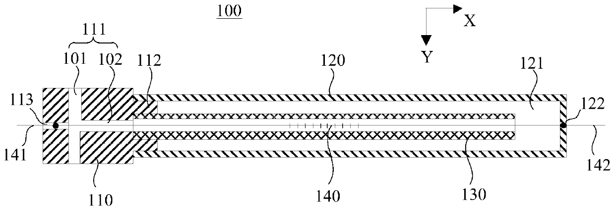
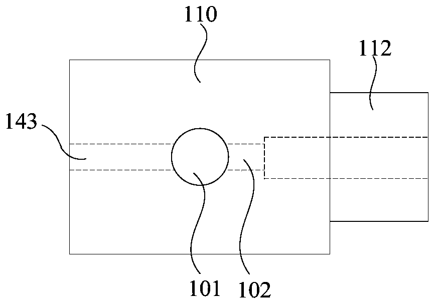
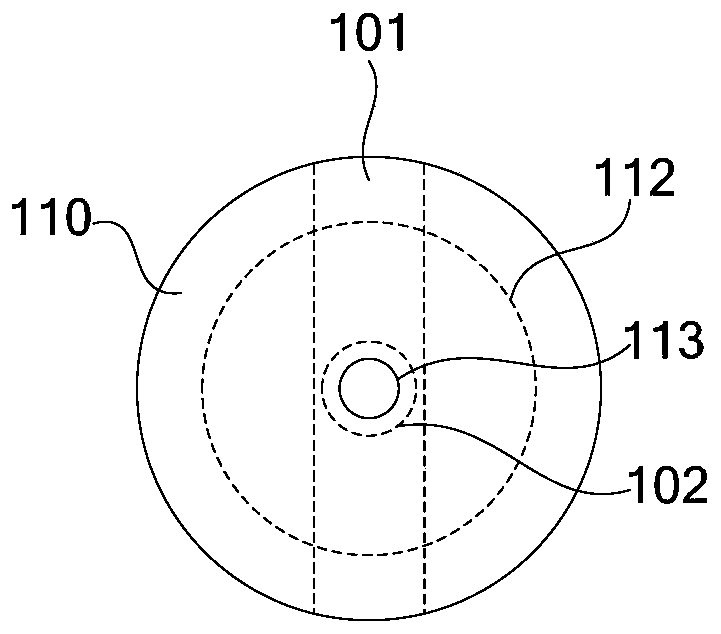
[0034] Such as figure 1 As shown, the first embodiment of the present invention provides a fiber grating hydrophone 100 , including a base 110 , an acoustic tube 120 , a balance tube 130 and a fiber grating 140 . The first end of the acoustic tube 120 is connected to the base 110 to form a cavity 121 . Both the balance tube 130 and the fiber grating 140 are disposed in the cavity 121 of the acoustic tube 120 . The base 110 is provided with a communication hole 111 for introducing external fluid into the cavity 121 . The first opening of the balance tube 130 communicates with the communication hole 111 , and the second opening of the balance tube 130 communicates with the cavity 121 , so that after the external fluid enters through the communication hole 111 , it flows into the cavity 121 through the balance tube 130 .
[0035]It should be noted that the sound-sensitive tube 120 and the base 110 may be integrally formed, or may be two independent components. In this embodime...
no. 2 example
[0059] Such as Figure 6 As shown, the second embodiment of the present invention also provides a sound pressure sensing system 10, including a light source device 200, a demodulation device 300, and the fiber Bragg grating hydrophone 100 provided in the above-mentioned first embodiment. Wherein, there may be one fiber grating hydrophone 100, or there may be several. Such as Figure 6 As shown, both the light source device 200 and the demodulation device 300 are optically coupled to the fiber Bragg grating 140 of the fiber Bragg grating hydrophone 100 , where the arrows are used to indicate optical signals. The detection light emitted by the light source device 200 enters the fiber grating 140, and the detection light reflected by the fiber grating 140 enters the demodulation device 300 as signal light carrying the sound pressure signal to be measured, and is demodulated by the demodulation device 300 to obtain the sound pressure to be measured.
[0060] In this embodiment, ...
PUM
 Abstract
Description
Claims
Application Information
 - R&D
- Intellectual Property
- Life Sciences
- Materials
- Tech Scout
- Unparalleled Data Quality
- Higher Quality Content
- 60% Fewer Hallucinations
Browse by: Latest US Patents, China's latest patents, Technical Efficacy Thesaurus, Application Domain, Technology Topic, Popular Technical Reports.
© 2025 PatSnap. All rights reserved.Legal|Privacy policy|Modern Slavery Act Transparency Statement|Sitemap|About US| Contact US: help@patsnap.com


