
Optical radar

A radar and optical technology, applied in the field of radar, can solve the problems of distance measurement error of the processor, the radar cannot judge the collision event normally, and the proportion of the error increases, so as to achieve the effect of correcting the error, improving the measurement stability and measurement accuracy.

Pending Publication Date: 2017-09-15
深圳市瑞大科技有限公司
View PDF4 Cites 5 Cited by
  • Summary
  • Abstract
  • Description
  • Claims
  • Application Information

AI Technical Summary

Problems solved by technology

[0004] In the process of realizing the present invention, the inventor found that the prior art has the following problems: due to the change of ambient temperature and the heating of the circuit part of the measurement system, a certain error will be generated in the distance measurement of the processor, especially when the distance is relatively short, the error accounts for The specific gravity will increase significantly, making it impossible for the radar to normally judge whether a collision event is about to occur

Method used


Image

  • Optical radar
  • Optical radar
  • Optical radar

Examples


Embodiment Construction

[0030] The following will clearly and completely describe the technical solutions in the embodiments of the present invention with reference to the accompanying drawings in the embodiments of the present invention. Obviously, the described embodiments are only part of the embodiments of the present invention, not all of them. Based on the embodiments of the present invention, all other embodiments obtained by persons of ordinary skill in the art without creative efforts fall within the protection scope of the present invention.

[0031] It should be noted that if there is a directional indication (such as up, down, left, right, front, back...) in the embodiment of the present invention, the directional indication is only used to explain the position in a certain posture (as shown in the accompanying drawing). If the specific posture changes, the directional indication will also change accordingly.

[0032] In addition, if there are descriptions involving "first", "second" and ...


PUM


Abstract

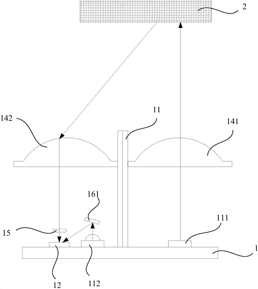
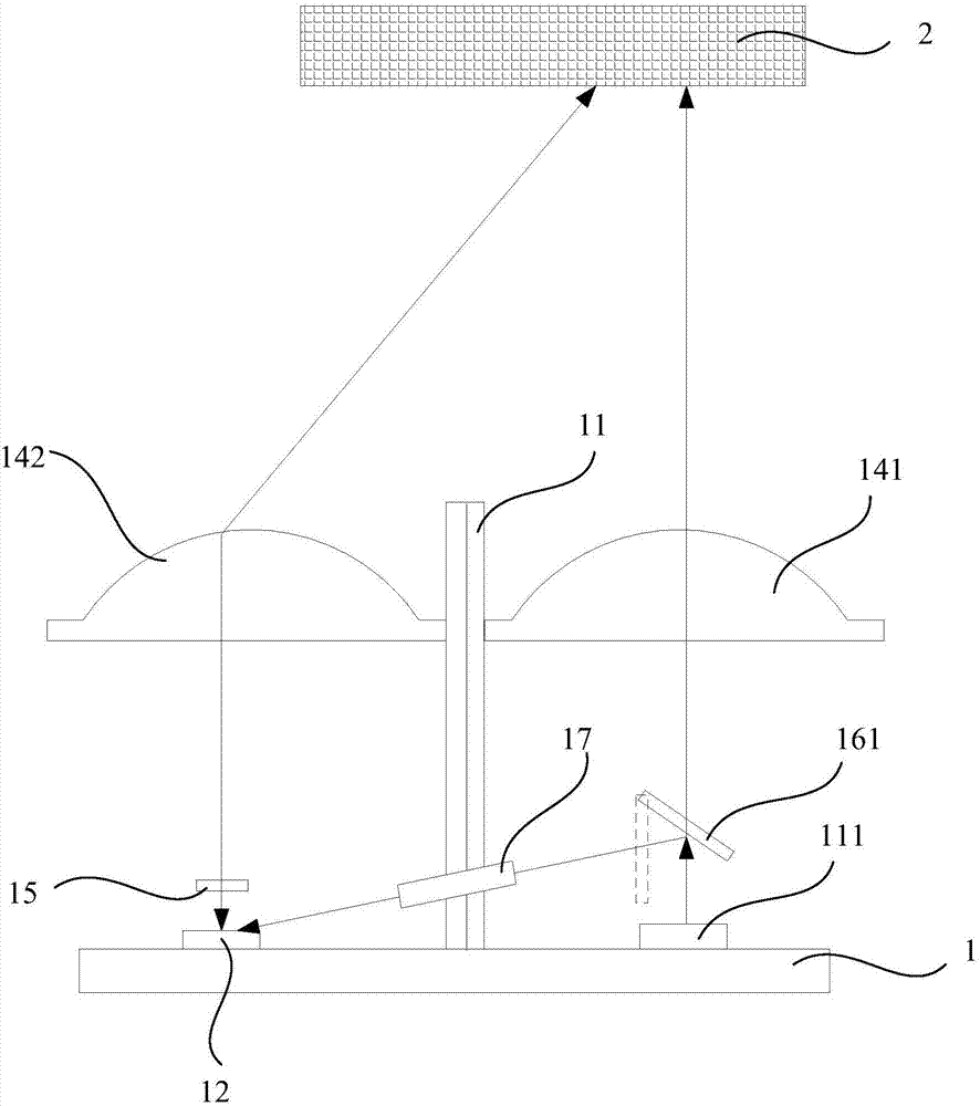
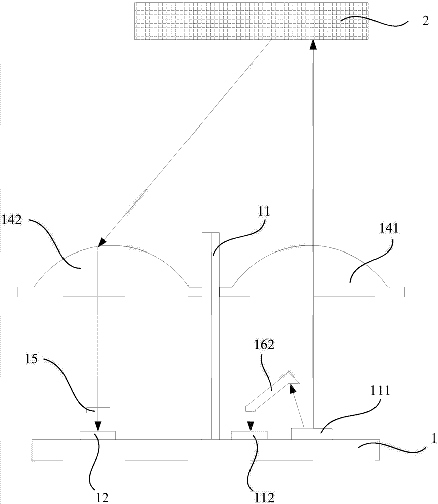
The invention discloses an optical radar. The optical radar includes a radar body, a light-emitting component, a light guiding element, a photoelectric receiving component and a processor; the light-emitting component is arranged on the radar body and emits a first light ray to a target object; the distance between the light guiding element and the radar body is a fixed value, and the light-emitting component emits a second light ray to the light guiding element; the photoelectric receiving component is arranged on the radar body and receives the first light ray reflected by the target object and the second light ray transmitted through the light guiding element, and converts the first light ray and the second light ray into electrical signals; and the processor is arranged on the radar body, is electrically connected with the photoelectric receiving component, and is used for calculating detection distance between the target object and the radar body and detection distance between the light guiding element and the radar body. The optical radar provided by the invention calibrates a system error of the optical radar by emitting the second light ray as a calibration light ray.

Description

technical field [0001] The invention relates to the field of radar, in particular to an optical radar. Background technique [0002] Radar is widely used to measure the distance between a target object and other objects, and the speed of other objects relative to the target object, such as the distance and relative speed between a moving car or an aircraft and surrounding obstacles. [0003] Taking the mainstream non-scanning optical radar in the market as an example, briefly introduce the working process of the optical radar: the non-scanning optical radar includes an emitter and a receiver. The illuminator generates and emits a pulse of light that hits an object and is reflected back, where it is finally received. The receiver accurately measures the travel time of the light pulse from when it is emitted to when it is reflected back. Given that the speed of light is known, the measured travel time can be converted into a measure of distance. [0004] In the process of r...

Claims


Application Information

Patent Timeline
Patent Type & Authority Applications(China)
IPC IPC(8): G01S17/08G01S17/10G01S7/497
CPCG01S7/497G01S17/08G01S17/10
Inventor 伍昕
Owner 深圳市瑞大科技有限公司
Learn More