
Structural heat transfer analysis finite element modeling method

A modeling method and finite element technology, applied in the field of modeling and analysis, can solve the problems of relatively few researches on key parameter identification methods of numerical model modeling methods, high experience requirements, and difficulty in obtaining accuracy, so as to achieve self-adaptation. The effect of identification and rapid model correction, improving modeling efficiency and ensuring analysis accuracy

Inactive Publication Date: 2017-09-15
SHANGHAI ELECTRICGROUP CORP
View PDF8 Cites 8 Cited by
  • Summary
  • Abstract
  • Description
  • Claims
  • Application Information

AI Technical Summary

Problems solved by technology

For example, Chinese patent CN105160092A discloses a thermal environment interpolation method suitable for the calculation of the transient temperature field of the protective system, Chinese patent CN104794277A provides a simulation method for the temperature field of rubber blocks that take into account cords, and Chinese patent CN102034006A discloses a A battery thermal management analysis and optimization method based on the finite element method, but at this stage, there are relatively few studies on the modeling method of the numerical model and the identification method of key parameters in the model
[0004] In the process of numerical simulation of the temperature field, the reasonable setting of key boundary condition parameters of the model is an important factor affecting the accuracy of the model, and the amount of such information provided by domestic patents is not sufficient
In view of the importance of the impact of boundary condition parameters on the accuracy of the finite element model, the usual method is to continuously correct the simulation model based on experimental data to meet the accuracy requirements, but this process not only requires high experience of analysts, but also requires a large number of repeated calculations The efficiency is relatively low, and it is difficult to obtain ideal accuracy when there are many boundary condition parameter variables

Method used


Image

  • Structural heat transfer analysis finite element modeling method
  • Structural heat transfer analysis finite element modeling method
  • Structural heat transfer analysis finite element modeling method

Examples


Embodiment Construction

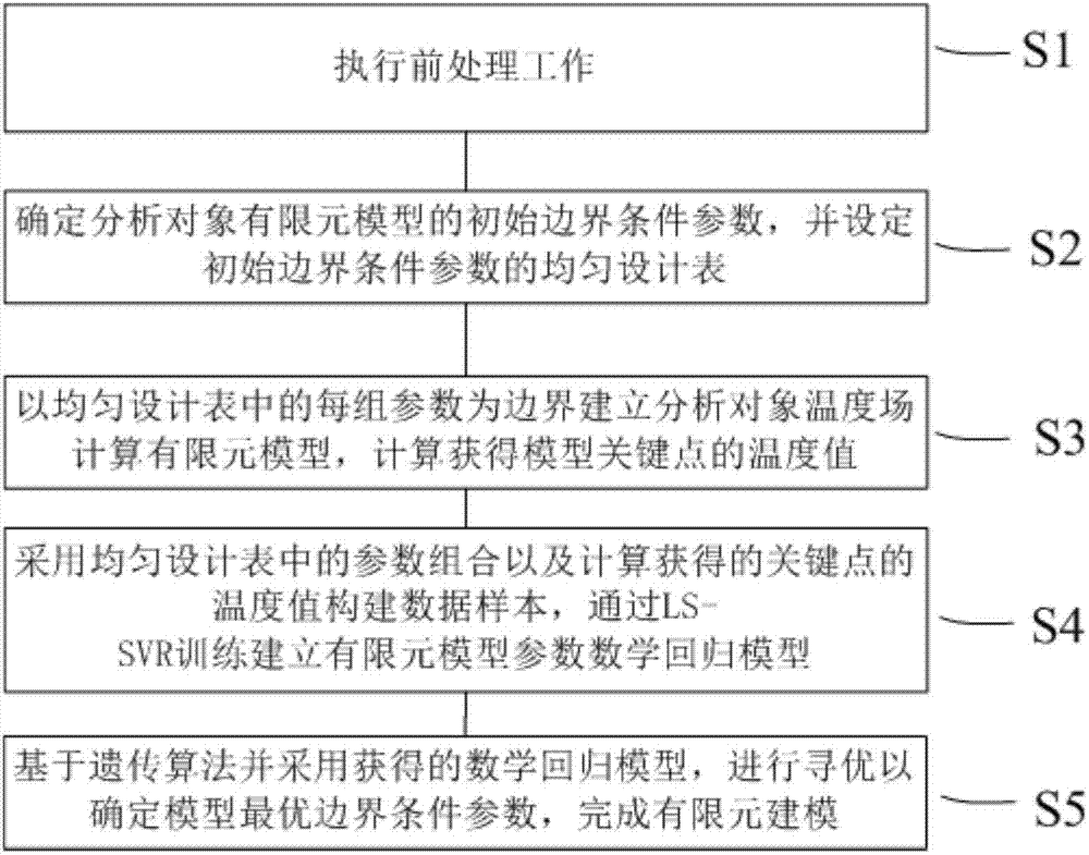
[0020] figure 1 It is a flowchart of a finite element modeling method for structural heat transfer analysis according to a preferred embodiment of the present invention.

[0021] Specifically as figure 1 As shown, the structural heat transfer analysis finite element modeling method according to the preferred embodiment of the present invention includes:

[0022] The first step S1: perform pre-processing work; for example, the pre-processing work includes: finite element mesh division of the analysis object, addition of material properties, and establishment of a uniform design table;

[0023] The second step S2: determine the initial boundary condition parameters of the finite element model of the analysis object, and set the uniform design table of the initial boundary condition parameters;

[0024] The third step S3: using each group of parameters in the uniform design table as the boundary to establish a finite element model for calculating the temperature field of the an...


PUM


Abstract

The invention discloses a structural heat transfer analysis finite element modeling method. The method comprises the following steps of: executing pre-processing work; determining initial boundary condition parameters of an analysis object finite element model and setting an uniform design table of the initial boundary condition parameters; establishing an analysis object temperature field calculation finite element model by taking each group of parameters in the uniform design table as a boundary, and carrying out calculation to obtain a temperature value of a model key point; constructing a data sample by adoption of parameter combination in the uniform design table and the calculated temperature value of the key point, and establishing a finite element model parameter mathematic regression model through LS-SVR training; and carrying out optimization to determine an optimum boundary condition parameter of the model on the basis of a genetic algorithm by adoption of the obtained mathematic regression model, so as to complete finite element modeling.

Description

technical field [0001] The invention relates to the field of temperature field numerical analysis, in particular to a modeling and analysis method that can effectively improve the accuracy of a temperature field finite element model and is easy to implement. Background technique [0002] The rationality of temperature field distribution and thermal stability of many products during operation are important factors affecting product performance. The influence of thermal factors in the product design and development stage is a key link to be considered. At this stage, numerical analysis methods are mostly used to obtain product performance. The distribution of temperature field and thermal stress provides parameter support for product design, operation and maintenance. Therefore, the accuracy of the numerical model for temperature field analysis of the product has a direct impact on product design and performance, while the rationality and accuracy of boundary condition paramet...

Claims


Application Information

Patent Timeline
IPC IPC(8): G06F17/50
CPCG06F30/23G06F2119/08
Inventor 李海伟徐欣付玉敏
Owner SHANGHAI ELECTRICGROUP CORP
Learn More