Dishwasher convenient to filter
A dishwasher and convenient technology, applied in the direction of washing machine/washing machine for tableware, washing machine/rinsing machine parts for tableware, cleaning equipment, etc. The effect of preventing local flow concentration, area reduction, and uniform passage
- Summary
- Abstract
- Description
- Claims
- Application Information
AI Technical Summary
Problems solved by technology
Method used
Image

Examples
Embodiment 1
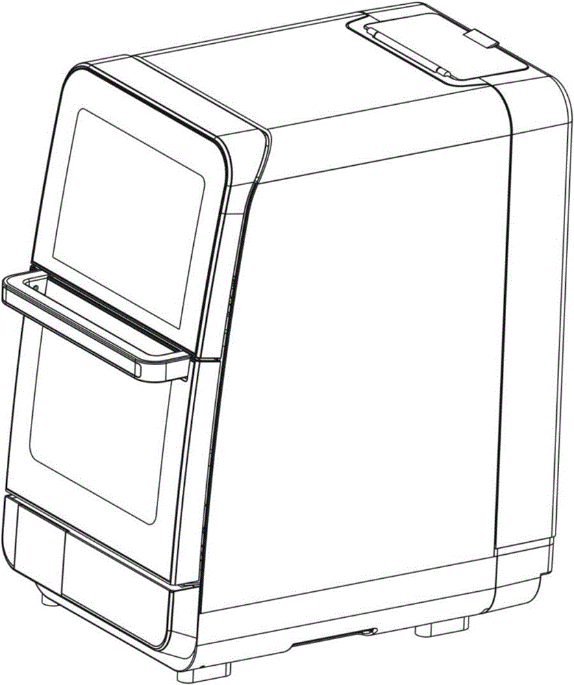
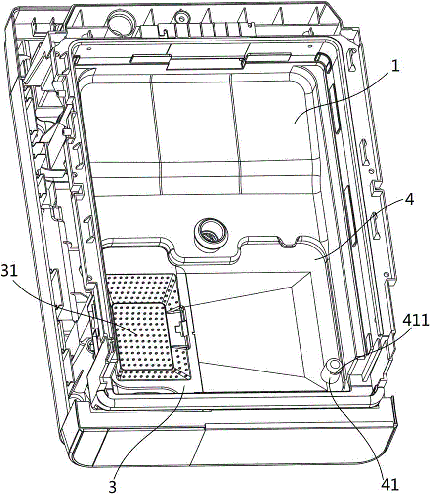
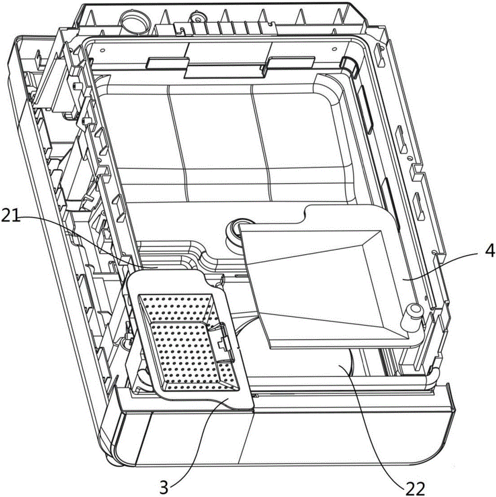
[0041] Such as Figure 1-5 As shown, the present embodiment 1 provides a dishwasher convenient for filtering, including an inner tank 1, a sump 2 and a circulation pump (not shown in the figure) are provided at the bottom of the inner tank 1, and the water inlet of the circulation pump is arranged at The bottom of the water collection tank 2, the water collection tank 2 includes a filter tank 21 and an overflow tank 22, the top of the filter tank 21 is covered with a filter plate 3, and the top of the overflow tank 22 is covered with an overflow tank cover plate 4 , the overflow tank 22 communicates with the filter tank 21, the filter plate 3 is provided with a plurality of filter holes 31, the overflow tank cover plate 4 is provided with an exhaust column 41, and the exhaust column 41 is provided with an exhaust hole 411 , and the exhaust hole 411 communicates with the overflow groove 22 . First of all, the dishwasher of the present invention is provided with an overflow tan...
Embodiment 2
[0055] The difference between this embodiment 2 and embodiment 1 is that, as Figure 6 As shown, the filter tank 21 is provided with a fine filter screen 6 located below the filter plate 3, and the filter plate 3 is provided with an inclined surface towards the fine filter screen 6, and the fine filter screen 6 can filter smaller impurities, The circulation pump pumps the circulating cleaning water with less impurities to avoid waterway blockage; the filter plate is inclined to help guide the cleaning water through the fine filter mesh to enhance the filtering effect.
[0056] Such as Figure 6 As shown, the filter plate 3 is provided with an installation port for installing a fine filter screen 6, and the fine filter screen 6 is fixed to the installation port by a fixing frame 7 and screws.
[0057] In other embodiments, after the filter plate is connected with the cover plate of the overflow tank, it can be formed into an inclined shape towards the fine filter screen, so as...
Embodiment 3
[0059] The difference between Embodiment 3 and Embodiment 1 is that the overflow tank is larger than the filter tank, and the water inlet of the circulation pump is arranged at the lower part of the overflow tank. Make the overflow tank larger than the filter tank, so that after the cleaning water enters the filter tank through the filter plate, the air inside the sump is squeezed into the overflow tank. Due to the large volume of the overflow tank, the air in the sump is allowed The air is slowly discharged from the exhaust column on the cover plate of the overflow tank, which solves the problems of rapid exhaust and easy blockage of the exhaust hole in the prior art, and is safer and more reliable; on the other hand, because the overflow tank is larger than the filter The water inlet of the circulating pump is set at the lower part of the overflow tank. Under the suction of the circulating pump, it helps to introduce the cleaning water from the filter tank into the overflow t...
PUM
 Abstract
Description
Claims
Application Information
 - R&D
- Intellectual Property
- Life Sciences
- Materials
- Tech Scout
- Unparalleled Data Quality
- Higher Quality Content
- 60% Fewer Hallucinations
Browse by: Latest US Patents, China's latest patents, Technical Efficacy Thesaurus, Application Domain, Technology Topic, Popular Technical Reports.
© 2025 PatSnap. All rights reserved.Legal|Privacy policy|Modern Slavery Act Transparency Statement|Sitemap|About US| Contact US: help@patsnap.com