Shield support without front beam of shield support and withdrawing method

A technology of shielding brackets and shielding beams, which is applied to mine roof brackets, earth-moving drilling, mining equipment, etc., can solve the problems of inconvenient movement and high quality, and achieve the effects of convenient movement, low resistance and improved safety factor.

Inactive Publication Date: 2017-09-19
HEILONGJIANG UNIVERSITY OF SCIENCE AND TECHNOLOGY
View PDF7 Cites 0 Cited by
  • Summary
  • Abstract
  • Description
  • Claims
  • Application Information

AI Technical Summary

Problems solved by technology

[0005] In order to solve the problem that the current cover hydraulic support must be provided with the front beam of the cover support, the present invention has large mass and inconvenient movement

Method used


Image

  • Shield support without front beam of shield support and withdrawing method
  • Shield support without front beam of shield support and withdrawing method
  • Shield support without front beam of shield support and withdrawing method

Examples


specific Embodiment approach 1

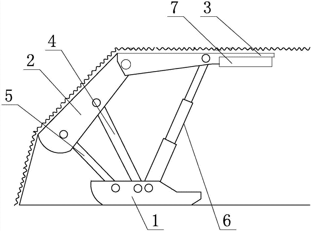
[0031] Specific implementation mode one: combine figure 2 To describe this embodiment,

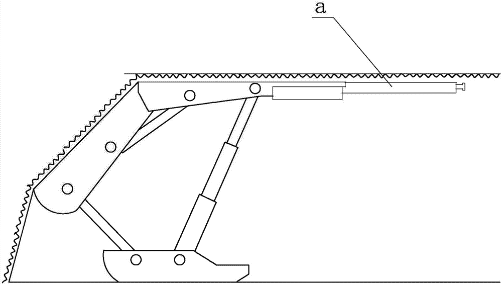
[0032] 1. A cover bracket for removing the front beam of the cover bracket, characterized in that it includes a base 1, a cover beam 2, a top beam 3, a cover beam hydraulic prop 4, a cover beam connecting plate or a cover beam connecting rod 5, and a top beam hydraulic column 6. One end of the base 1 is fixed or hinged to one end of the cover beam connecting plate or the cover beam connecting rod 5, and the middle part of the base 1 is fixed or hinged to the lower end of the top beam hydraulic column 6; one end of the cover beam 2 is hinged to the cover beam The other end of the connecting plate or the cover beam connecting rod 5; the other end of the cover beam 2 is hinged to one end of the roof beam 3, and the other end of the roof beam 3 is the edge of the roof beam. The middle part of the beam 3 hinges the top of the top beam hydraulic column 6; the length of the top beam 3 is 2.1 me...

specific Embodiment approach 2

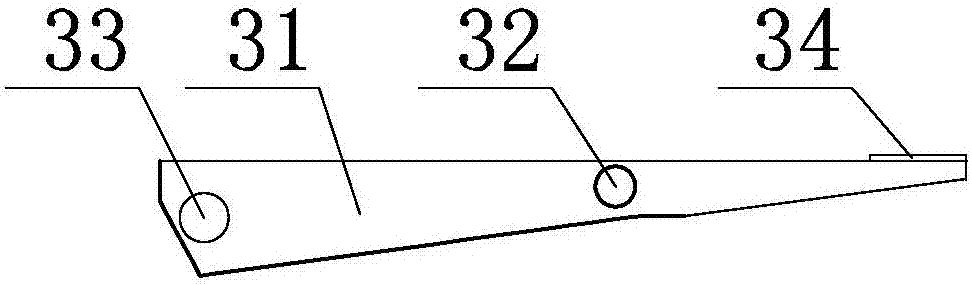
[0035] Specific implementation mode two: combination image 3 and Figure 4 To describe this embodiment,

[0036] The roof beam 3 in this embodiment includes a roof beam rotation shaft 33, a roof beam support shaft 32 and a plurality of roof beam arms 31; And can rotate relative to the top beam arm 31, the top of the top beam hydraulic column 6 is hinged with the middle part of the top beam support shaft 32 and the top beam 3; The top beam arm 31 rotates relatively, and the other end of the shield beam 2 is hinged to the top beam 3 through the top beam rotation axis 33 .

[0037] Other structures and parameters are the same as those in the first embodiment.

specific Embodiment approach 3

[0038] The top beam arms 31 in this embodiment are connected with lacing plates 34 on their upper ends.

[0039] Other structures and parameters are the same as in the second embodiment.


PUM


Abstract

The invention discloses a shield support without a front beam of the shield support and a withdrawing method and relates to a shield hydraulic support and a withdrawing method by means of the shield support. The invention aims to solve the problem that an existing shield hydraulic bracket needs to be provided with the front beam of the shield support, which is large in weight and inconvenient to move. One end of a base is fixedly connected or hinged to one end of a shield beam connecting plate or a shield beam connecting rod, and the middle of the base is fixedly connected or hinged to the low end of a top beam hydraulic column; one end of the shield beam is hinged to the other end of the shield beam connecting plate or the shield beam connecting rod; the other end of the shield beam is hinged to one end of the top beam while the other end of the top beam is a top beam edge which is not connected to any devices, and the middle of the top beam is hinged to the top end of the top beam hydraulic column; the top beam is 2.1m long; and one end of the shield beam hydraulic support column is hinged to the middle of the shield beam while the other end of the shield beam hydraulic support column is hinged to the base. The shield support disclosed by the invention is suitable for the withdrawing operation of a hydraulic bracket on an underground coal face.

Description

technical field [0001] The invention relates to a cover type hydraulic support and a method for withdrawing using the cover support. Background technique [0002] The relocation of the fully mechanized mining face is an important production preparation work in the mine, and it is also an important link to achieve efficient and safe production. At present, the most important work in the relocation process of the fully mechanized mining face is the withdrawal of the hydraulic support of the working face. The hydraulic support of the working face has the characteristics of large volume and high quality. How to quickly return it under the premise of ensuring the safety of the roof of the working face Withdrawal of supports, shortening the relocation period of the working face, and satisfying the normal replacement of the working face are the key to the retraction of the working face. [0003] With the increase of comprehensive mechanized coal mining faces, the speed of fully me...

Claims


Application Information

Patent Timeline
Patent Type & Authority Applications(China)
IPC IPC(8): E21D23/04E21D23/06E21D23/16
CPCE21D23/04E21D23/06E21D23/16
Inventor 肖福坤郝传波刘刚蒋元男刘志军秦宪礼
Owner HEILONGJIANG UNIVERSITY OF SCIENCE AND TECHNOLOGY
Why Eureka
Try Eureka