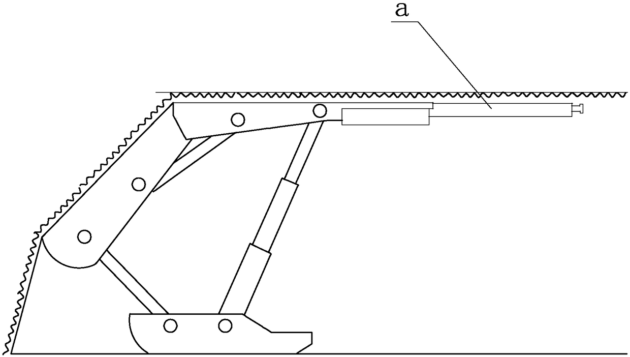
A kind of cover support and withdrawal method for removing the front beam of the cover support
A technology for shielding brackets and front beams, which is applied to mine roof brackets, earth-moving drilling, mining equipment, etc., can solve the problems of large mass and inconvenient movement, and achieve the effects of low resistance, convenient movement and weight reduction.
- Summary
- Abstract
- Description
- Claims
- Application Information
AI Technical Summary
Problems solved by technology
Method used
Image
Examples
specific Embodiment approach 1
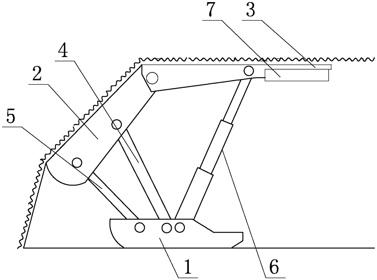
[0031] Specific implementation mode one: combine figure 2 To describe this embodiment,
[0032] 1. A cover bracket for removing the front beam of the cover bracket, characterized in that it includes a base 1, a cover beam 2, a top beam 3, a cover beam hydraulic prop 4, a cover beam connecting plate or a cover beam connecting rod 5, and a top beam hydraulic column 6. One end of the base 1 is fixed or hinged to the shield beam connecting plate or one end of the shield beam connecting rod 5, and the middle part of the base 1 is fixed or hinged to the bottom end of the top beam hydraulic column 6; one end of the shield beam 2 is hinged to the shield beam The other end of the connecting plate or the cover beam connecting rod 5; the other end of the cover beam 2 is hinged to one end of the roof beam 3, and the other end of the roof beam 3 is the edge of the roof beam. The middle part of the beam 3 hinges the top of the top beam hydraulic column 6; the length of the top beam 3 is 2...
specific Embodiment approach 2
[0035] Specific implementation mode two: combination image 3 with Figure 4 To describe this embodiment,
[0036] The roof beam 3 in this embodiment includes a roof beam rotation shaft 33, a roof beam support shaft 32 and a plurality of roof beam arms 31; And can rotate relative to the top beam arm 31, the top of the top beam hydraulic column 6 is hinged with the middle part of the top beam support shaft 32 and the top beam 3; The top beam arm 31 rotates relatively, and the other end of the shield beam 2 is hinged to the top beam 3 through the top beam rotation axis 33 .
[0037] Other structures and parameters are the same as those in the first embodiment.
specific Embodiment approach 3
[0038] The top beam arms 31 in this embodiment are connected with lacing plates 34 on their upper ends.
[0039] Other structures and parameters are the same as in the second embodiment.
PUM
 Abstract
Description
Claims
Application Information
 - R&D
- Intellectual Property
- Life Sciences
- Materials
- Tech Scout
- Unparalleled Data Quality
- Higher Quality Content
- 60% Fewer Hallucinations
Browse by: Latest US Patents, China's latest patents, Technical Efficacy Thesaurus, Application Domain, Technology Topic, Popular Technical Reports.
© 2025 PatSnap. All rights reserved.Legal|Privacy policy|Modern Slavery Act Transparency Statement|Sitemap|About US| Contact US: help@patsnap.com


