
Method and apparatus for detecting state of switch

A technology for detecting switches and switch states, which is applied in the direction of circuit breaker testing, etc., can solve the problems of ADC port consumption, high power consumption of resistors, unfavorable detection, etc., to save CPU resources, reduce port occupation, and reduce debounce time Effect

Inactive Publication Date: 2017-09-19
SCHNEIDER ELECTRIC IND SAS
View PDF7 Cites 1 Cited by
  • Summary
  • Abstract
  • Description
  • Claims
  • Application Information

AI Technical Summary

Problems solved by technology

However, this method typically requires a resistor in series with the switch under test for detection
Resistors typically dissipate significant power and the resulting heat can adversely affect device performance and operation
In addition, the conventional method has many other problems, for example, it is not conducive to the detection of a wide voltage range (for example, in the case of SD state), the interlocked switching signals cannot be detected at the same time, the detection speed is slow, the response is slow, the ADC port is consumed, and the CPU resources, etc.

Method used


Image

  • Method and apparatus for detecting state of switch
  • Method and apparatus for detecting state of switch
  • Method and apparatus for detecting state of switch

Examples


Embodiment Construction

[0022] The principle and spirit of the present disclosure will be described below with reference to several exemplary embodiments shown in the accompanying drawings. It should be understood that these implementations are described only to enable those skilled in the art to better understand and implement the present disclosure, but not to limit the scope of the present disclosure in any way.

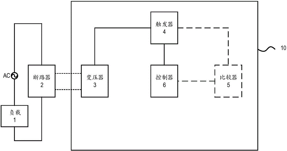
[0023] figure 1 The detection device 10 and its application scenarios according to the embodiments of the present disclosure are shown. Such as figure 1 As shown, a power source (for example, an AC power source) supplies power to a load 1 through a circuit breaker 2 . The detection device 10 can be connected with the switch in the circuit breaker 2 to determine the state of the switch, so as to detect the states such as OF, SD, and SDE.

[0024] By using a transformer instead of the conventional resistance voltage division detection method, the power consumption is greatly reduced, th...


PUM


Abstract

The embodiment of the disclosure relates to a method and apparatus for detecting the state of a switch. The apparatus comprises a transformer, a trigger, and a controller. A primary winding of the transformer is coupled to the switch electrically; the trigger coupled to a secondary winding electrically is configured to respond to a trigger signal and generate a response signal associated with the switching state of the switch; and the controller is configured to generating the trigger signal and generating a switching signal for expressing the state of the switch based on the response signal.

Description

technical field [0001] Embodiments of the present disclosure relate to the field of power detection, and more particularly to apparatus and methods for detecting the state of a switch. Background technique [0002] In the field of power detection, it is usually necessary to determine the states of various switches (especially wet-junction switches). For example, for a circuit breaker, it may be necessary to determine the status of OF, SD, etc. [0003] Conventional switch state detection methods and devices usually use an optocoupler to isolate the switch to be tested from the detection circuit. However, this approach typically requires a resistor in series with the switch under test for detection. Resistors typically dissipate significant power, and the resulting heat can adversely affect device performance and operation. In addition, the conventional method has many other problems, for example, it is not conducive to the detection of a wide voltage range (for example, i...

Claims


Application Information

Patent Timeline
Patent Type & Authority Applications(China)
IPC IPC(8): G01R31/327
CPCG01R31/327
Inventor 陈加敏刘凯石莹王舜尧赵海军吴蔚A·雷特
Owner SCHNEIDER ELECTRIC IND SAS
Learn More