Bill discrimination method, device and equipment, and storage medium
A bill and fluorescence technology, applied in the field of image processing, can solve the problems of low bill identification efficiency, achieve the effects of reducing time complexity, improving identification rate, and improving identification efficiency
- Summary
- Abstract
- Description
- Claims
- Application Information
AI Technical Summary
Problems solved by technology
Method used
Image
Examples
Embodiment 1
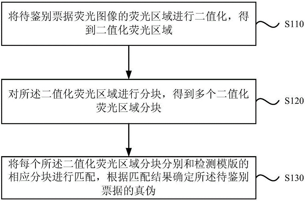
[0064] Please refer to the attached figure 1 , is a schematic flow chart of a bill identification method provided by Embodiment 1 of the present invention. This method is applicable to the scene of banks or financial institutions conducting anti-counterfeit identification of valuable notes. The method is executed by a bill identification device, which can be controlled by software and / or hardware implementation, which can be integrated inside the bill validator or financial transaction equipment. The method specifically includes the following steps:
[0065] S110. Binarize the fluorescent area of the fluorescent image of the bill to be identified to obtain a binarized fluorescent area.
[0066] It should be noted that the fluorescent image of the bill to be identified refers to the image of the bill to be identified under the irradiation of an ultraviolet light source, which can be obtained using an image acquisition device, and the fluorescent area is an area with a fluor...
Embodiment 2
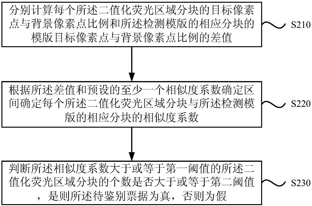
[0077] figure 2 It is a schematic flow chart of a bill identification method provided by Embodiment 2 of the present invention. On the basis of the above-mentioned embodiments, this embodiment "blocks each of the binarized fluorescent regions and detects the corresponding blocks of the template." Perform matching, and determine the authenticity of the bill to be identified according to the matching result" was optimized. The method specifically may include the following steps:
[0078] S210. Calculate the difference between the ratio of the target pixel point to the background pixel point of each of the binarized fluorescence region blocks and the ratio of the template target pixel point to the background pixel point of the corresponding block of the detection template.
[0079] It should be noted that, in general, if there is no signal deviation or signal interference during image acquisition, the number of pixels in the binarized fluorescent area block of the bill to be id...
Embodiment 3
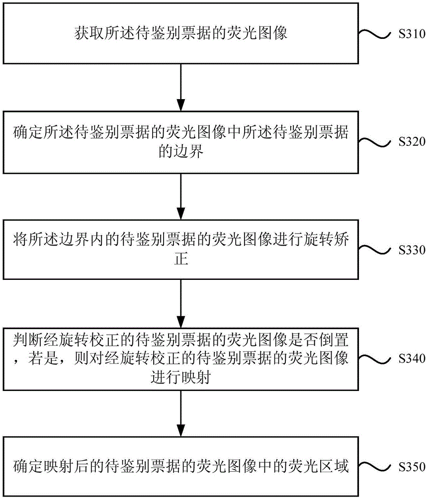
[0092] image 3 It is a schematic flowchart of a bill identification method provided by Embodiment 3 of the present invention, and this embodiment is optimized on the basis of the foregoing embodiments. The method specifically may include the following steps:
[0093] S310. Acquire a fluorescent image of the bill to be identified.
[0094] Specifically, the fluorescent image of the bill to be identified can be obtained by using an image acquisition device, and the image acquisition device can be a camera or a terminal device equipped with a camera, such as an image sensor. Specifically, what the image acquisition device acquires is The image of the bill to be authenticated under the irradiation of ultraviolet light source.
[0095] S320. Determine a boundary of the bill to be identified in the fluorescent image of the bill to be identified.
[0096] Specifically, the boundary point of the bill to be identified can be found by using the method of boundary tracking, and then ...
PUM
 Abstract
Description
Claims
Application Information
 - R&D
- Intellectual Property
- Life Sciences
- Materials
- Tech Scout
- Unparalleled Data Quality
- Higher Quality Content
- 60% Fewer Hallucinations
Browse by: Latest US Patents, China's latest patents, Technical Efficacy Thesaurus, Application Domain, Technology Topic, Popular Technical Reports.
© 2025 PatSnap. All rights reserved.Legal|Privacy policy|Modern Slavery Act Transparency Statement|Sitemap|About US| Contact US: help@patsnap.com


