
Solenoid assembly for solenoid directional valve

An electromagnetic reversing valve, electromagnet technology, applied in the direction of an electromagnet with an armature, an electromagnet, etc., can solve the problems of reducing the electromagnetic conversion efficiency, the surface of the coil is not easy to dissipate heat, and easy to generate eddy current phenomenon, so as to improve the electromagnetic conversion efficiency, Conducive to the effect of heat dissipation and eddy current reduction

Active Publication Date: 2019-09-24
CHANGZHOU KANGSHIDA ELECTROMECHANICAL CO LTD
View PDF9 Cites 0 Cited by
  • Summary
  • Abstract
  • Description
  • Claims
  • Application Information

AI Technical Summary

Problems solved by technology

[0002] The electromagnet assembly of the electromagnetic reversing valve used in existing engineering vehicles (including forklifts, tractors, loaders, etc.) includes a first iron core, a second iron core, a yoke, a coil and an insulating protective layer. The yoke is a ring structure, and the yoke fits snugly on the outer circumference of the coil, and then the insulating protective layer is packaged on the outer circumference of the yoke, so that not only the positioning of each component must be ensured during the packaging process, but also the coil The surface is not easy to dissipate heat, and it is easy to generate eddy current phenomenon, which reduces the electromagnetic conversion efficiency

Method used


Image

  • Solenoid assembly for solenoid directional valve
  • Solenoid assembly for solenoid directional valve
  • Solenoid assembly for solenoid directional valve

Examples


Embodiment Construction

[0024] The present invention will be further described below in conjunction with the accompanying drawings and given embodiments, but is not limited thereto.

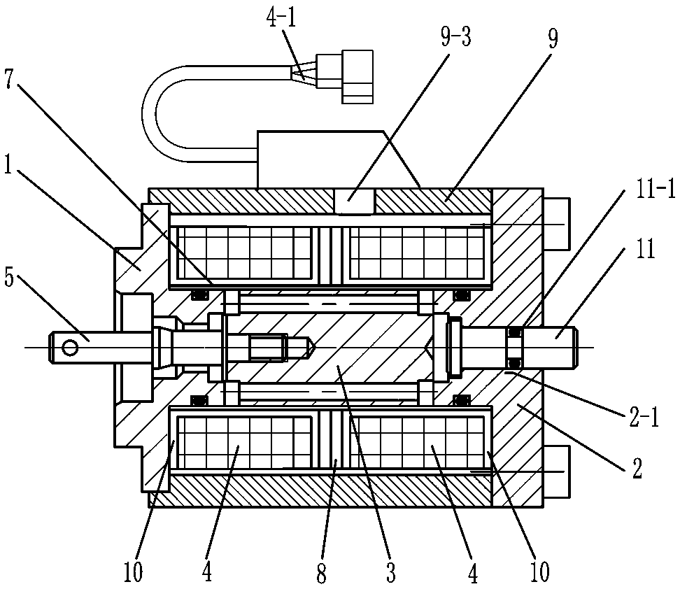
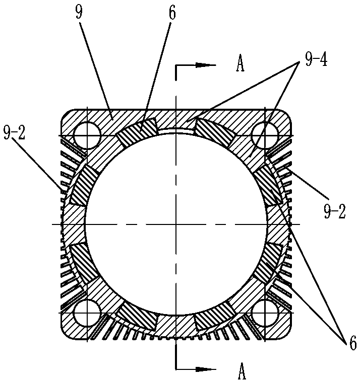
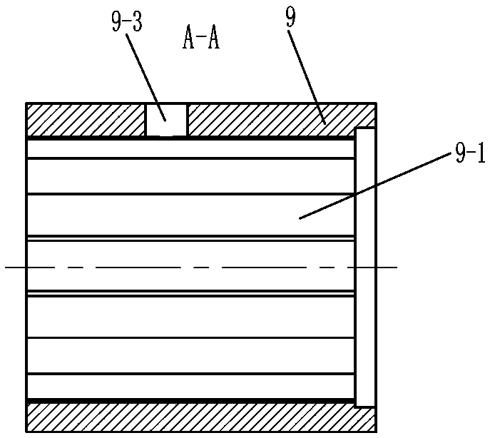
[0025] Such as figure 1 , 2 , 3, 4, 5, and 6, an electromagnet assembly of an electromagnetic reversing valve includes a first iron core 1, a second iron core 2, a push-pull rod 5 and a heat dissipation support 9, and a heat dissipation support 9 Axially install the armature 3, the coil 4, the yoke 6, the magnetic isolation sleeve 7 and the magnetic conduction ring 8 in the through hole 9-1;

[0026] The first iron core 1 and the second iron core 2 are respectively arranged at both ends of the heat dissipation support 9;

[0027] One end of the armature 3 is assembled or integrated with one end of the push-pull rod 5, and the two ends of the magnetic isolation sleeve 7 are respectively assembled, connected or welded on the first iron core 1 and the second iron core 2, and the magnetic isolation The sleeve 7 is locate...


PUM


Abstract

The invention relates to an electromagnet assembly of a magnetic exchange valve. The electromagnet assembly comprises a first iron core, a second iron core, a push-pull rod, a cooling bracket, an armature, coils, a magnetic yoke, a magnetic isolating sleeve and a magnetic conducting ring, wherein the armature, the coils, the magnetic yoke, the magnetic isolating sleeve and the magnetic conducting ring are arranged in an axial installation through hole of the cooling bracket; the first iron core and the second iron core are arranged at two ends of the cooing bracket separately; one end of the armature and one end of the push-pull rod are assembled or manufactured into a whole; two ends of the magnetic isolating sleeve are assembled or welded on the first iron core and the second iron core separately and the magnetic isolating sleeve is located on the periphery of the armature; and two coils are arranged on the periphery of the magnetic isolating sleeve and the magnetic conducting ring is arranged between the two coils. The electromagnet assembly is characterized in that the magnetic yoke is formed by two or more strip-shaped magnetic yokes; two or more strip-shaped magnetic yoke slots are formed in the inner wall of the cooling bracket; and the strip-shaped magnetic yokes are embedded into the strip-shaped magnetic yoke slots separately. The electromagnet assembly has the advantages that the eddy current phenomenon can be reduced, heat dissipation of the coils is facilitated and the electromagnetic conversion efficiency is improved.

Description

technical field [0001] The invention relates to an electromagnetic reversing valve, in particular to an electromagnet assembly of an electromagnetic reversing valve used in engineering vehicles. Background technique [0002] The electromagnet assembly of the electromagnetic reversing valve used in existing engineering vehicles (including forklifts, tractors, loaders, etc.) includes a first iron core, a second iron core, a yoke, a coil and an insulating protective layer. The yoke is a ring structure, and the yoke fits snugly on the outer circumference of the coil, and then the insulating protective layer is packaged on the outer circumference of the yoke, so that not only the positioning of each component must be ensured during the packaging process, but also the coil The surface is not easy to dissipate heat, and it is easy to generate eddy current phenomenon, which reduces the electromagnetic conversion efficiency. Contents of the invention [0003] The purpose of the pr...

Claims


Application Information

Patent Timeline
Patent Type & Authority Patents(China)
IPC IPC(8): H01F7/08H01F7/16H01F7/06
Inventor 王小康岳烨冬盛建新
Owner CHANGZHOU KANGSHIDA ELECTROMECHANICAL CO LTD
Learn More