

Port binding method and device
A technology of port binding and implementation method, applied in the field of communication, to achieve the effect of link backup
- Summary
- Abstract
- Description
- Claims
- Application Information
AI Technical Summary
Problems solved by technology
Method used
Image

Examples
Embodiment 1
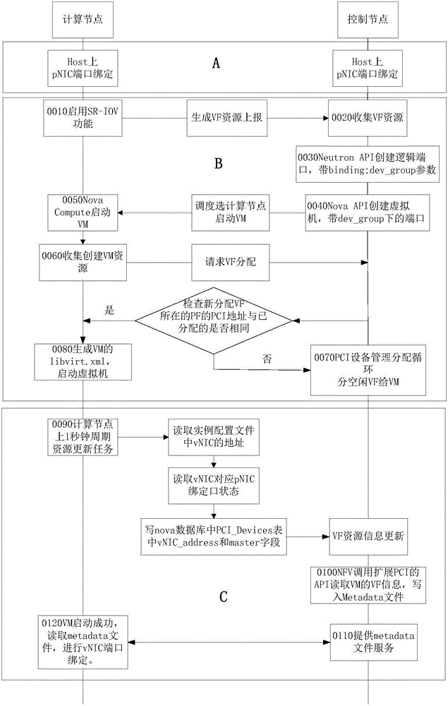
[0050]This embodiment provides a method for implementing port binding, which is applied to an SR-IOV virtualized network, and the method includes:
[0051] Create SR-IOV logical ports, and the logical ports under the same aggregation port belong to the same binding group;
[0052] Create a virtual machine and select a virtual function VF to assign to the virtual machine, so that the physical function PFs where the VFs of the same binding group reside are different.
[0053] In this embodiment, an SR-IOV logical port is created, and the logical ports under the same aggregation port belong to the same binding group, a virtual machine is created, and a virtual function VF is selected to be assigned to the virtual machine, so that the VF of the same binding group is located PFs with different physical functions, the technical solution of the present invention can overcome the problem in the prior art that VFs come from the same PF when vNIC ports of virtual machines are aggregated...
Embodiment 2
[0080] This embodiment provides a device for implementing port binding, which is applied in an SR-IOV virtualized network, and the device includes:
[0081] The first creation module is used to create SR-IOV logical ports, and the logical ports under the same aggregation port belong to the same binding group;
[0082] The second creation module is used to create a virtual machine, and select a virtual function VF to assign to the virtual machine, so that the physical functions PF where the VFs of the same binding group are located are different.
[0083] In this embodiment, an SR-IOV logical port is created, and the logical ports under the same aggregation port belong to the same binding group, a virtual machine is created, and a virtual function VF is selected to be assigned to the virtual machine, so that the VF of the same binding group is located PFs with different physical functions, the technical solution of the present invention can overcome the problem in the prior art...
Embodiment 3
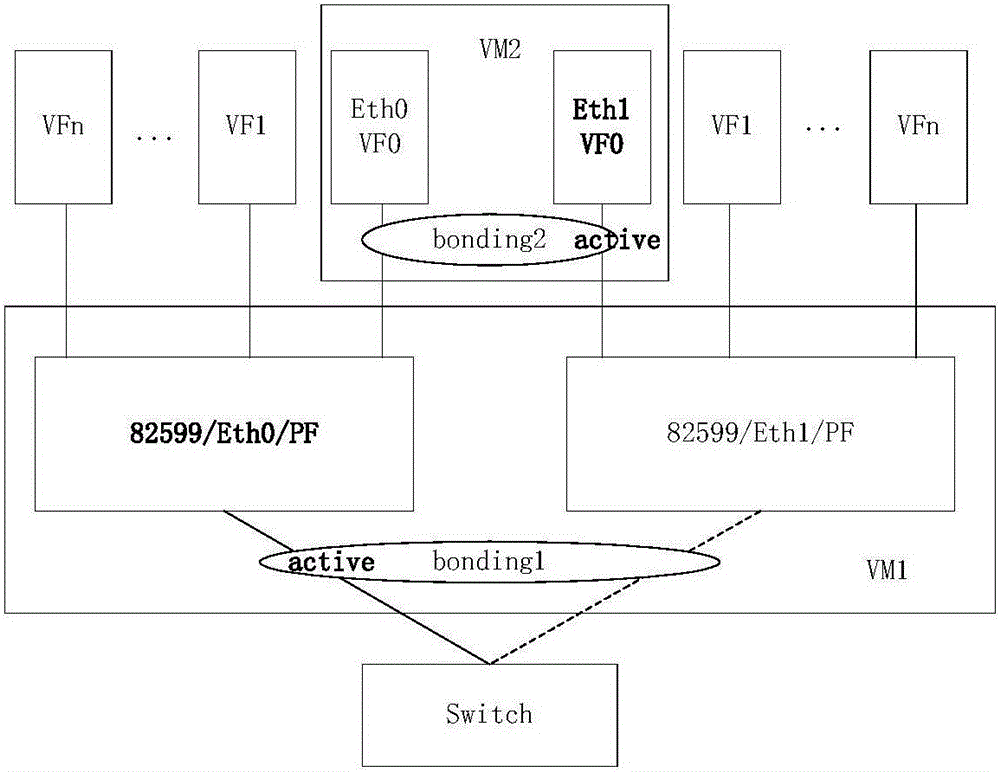
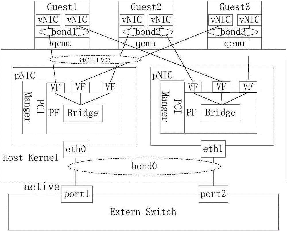
[0087] In this embodiment, the SR-IOV function is enabled in the cloud computing virtual network, and the following functions can be realized in the binding method of PF and VF:
[0088] Function A: PF port binding;
[0089] Function B: VF port binding member port selection;
[0090] Specifically, neutron (a module in openstack used to create a virtual network) introduces binding group parameters when creating a port; nova creates a virtual machine, and assigns VF members of the binding group to come from different PFs.
[0091] Function C: The PF binding interface is consistent with the VF interface binding main interface.
[0092] Specifically, the port PCI (logical port defines the standard of the local bus) address of the VM and the active / standby status of the PF are added to the nova database, and the PCI of the vNIC inside the VM is added to the API (application programming interface) for nova querying the PCI information of the VM. The address and the corresponding P...
PUM
 Abstract
Description
Claims
Application Information