
Deploying virtual machine to host based on workload characterizations

a virtual machine and workload technology, applied in computing, program control, instruments, etc., can solve the problems of difficult to justify upgrading the hardware to a more modern, faster system, and nearing the end of the life of the hardware, and achieve the goal of optimizing hardware usage. difficult if not impossible to achiev

Inactive Publication Date: 2007-11-22
MICROSOFT TECH LICENSING LLC
View PDF19 Cites 421 Cited by
  • Summary
  • Abstract
  • Description
  • Claims
  • Application Information

AI Technical Summary

Benefits of technology

[0010]A sub-rating is calculated for each of several resources available from the candidate host, where the sub-rating for the resource corresponds to an amount of the resource that is free after the candidate VM is deployed to the candidate host. Thereafter, a rating is calculated from the calculated sub-ratings to characterize how well the candidate host can accommodate the candidate VM. The rating for each candidate host is presented to a selector that determines whether to deploy the candidate VM to the candidate host based on the rating thereof. A selection of the candidate host is received for deployment of the candidate VM thereon, and the resources of the selected host as required by the candidate VM are reserved until the candidate VM is deployed to the selected host. Thereafter, the candidate VM is deployed to the selected host.

Problems solved by technology

More specifically, a typical user has many server machines and the like that run varied workloads which do not fully utilize the underlying hardware.
Furthermore, some of the hardware is nearing end of life and it may be difficult to justify upgrading the hardware to a more modern, faster system when the existing hardware is not fully utilized.
If deployment is inefficient or allows for incompatible matches of resources to requirements, the goal of optimizing hardware usage becomes difficult if not impossible to achieve.

Method used


Image

  • Deploying virtual machine to host based on workload characterizations
  • Deploying virtual machine to host based on workload characterizations
  • Deploying virtual machine to host based on workload characterizations

Examples


Embodiment Construction

Computer Environment

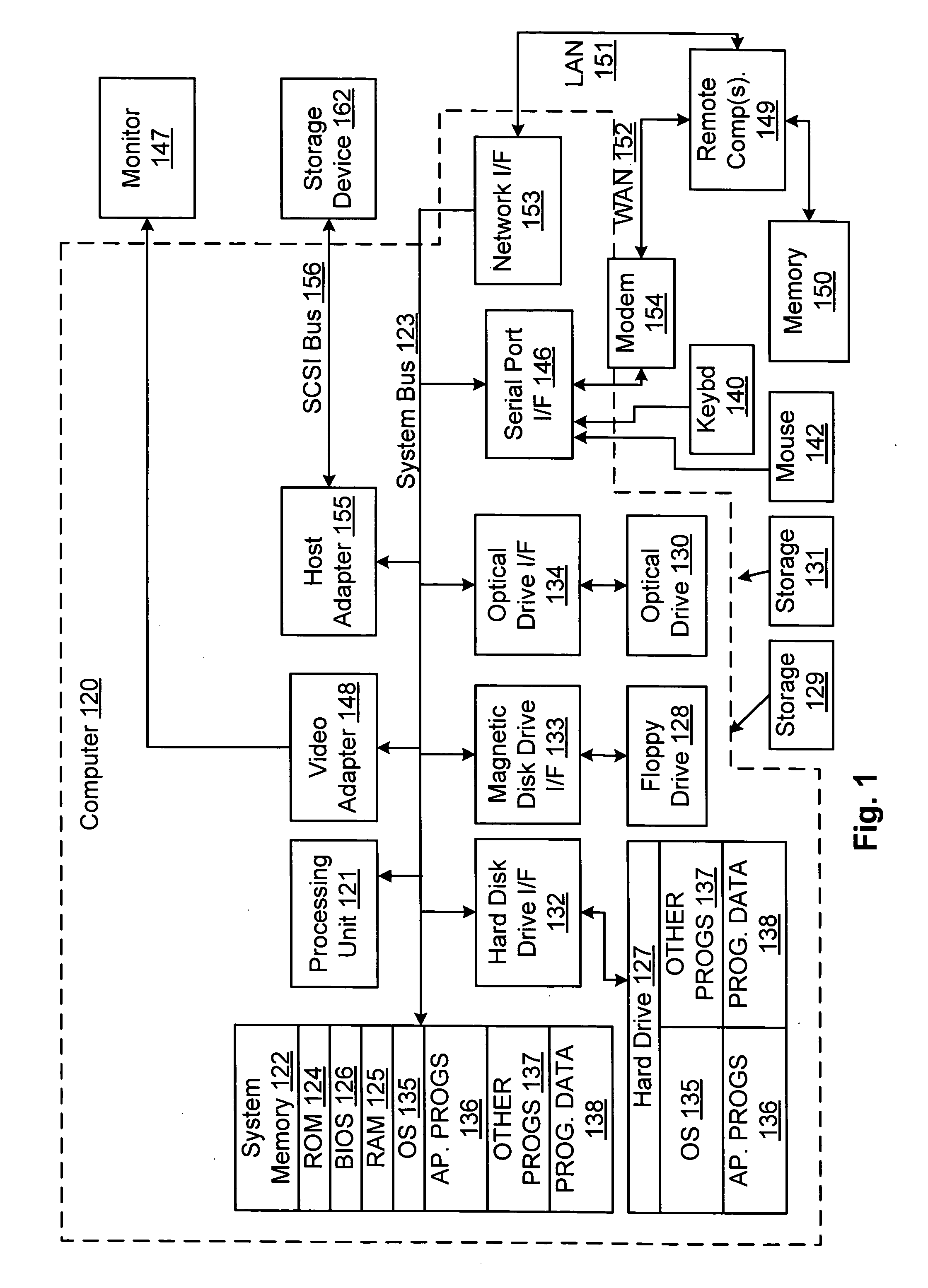
[0018]FIG. 1 and the following discussion are intended to provide a brief general description of a suitable computing environment in which the present invention and / or portions thereof may be implemented. Although not required, the invention is described in the general context of computer-executable instructions, such as program modules, being executed by a computer, such as a client workstation or a server. Generally, program modules include routines, programs, objects, components, data structures and the like that perform particular tasks or implement particular abstract data types. Moreover, it should be appreciated that the invention and / or portions thereof may be practiced with other computer system configurations, including hand-held devices, multi-processor systems, microprocessor-based or programmable consumer electronics, network PCs, minicomputers, mainframe computers and the like. The invention may also be practiced in distributed computing environment...


PUM


Abstract

To determine whether to deploy a candidate VM to a candidate host, taking into consideration resources available from the candidate host and resources required by the candidate VM, a sub-rating is calculated for each of several resources available from the candidate host, where the sub-rating for the resource corresponds to an amount of the resource that is free after the candidate VM is deployed to the candidate host. Thereafter, a rating is calculated from the calculated sub-ratings to characterize how well the candidate host can accommodate the candidate VM. The rating for the candidate host are presented to a selector that determines whether to deploy the candidate VM to the candidate host based on the rating thereof.

Description

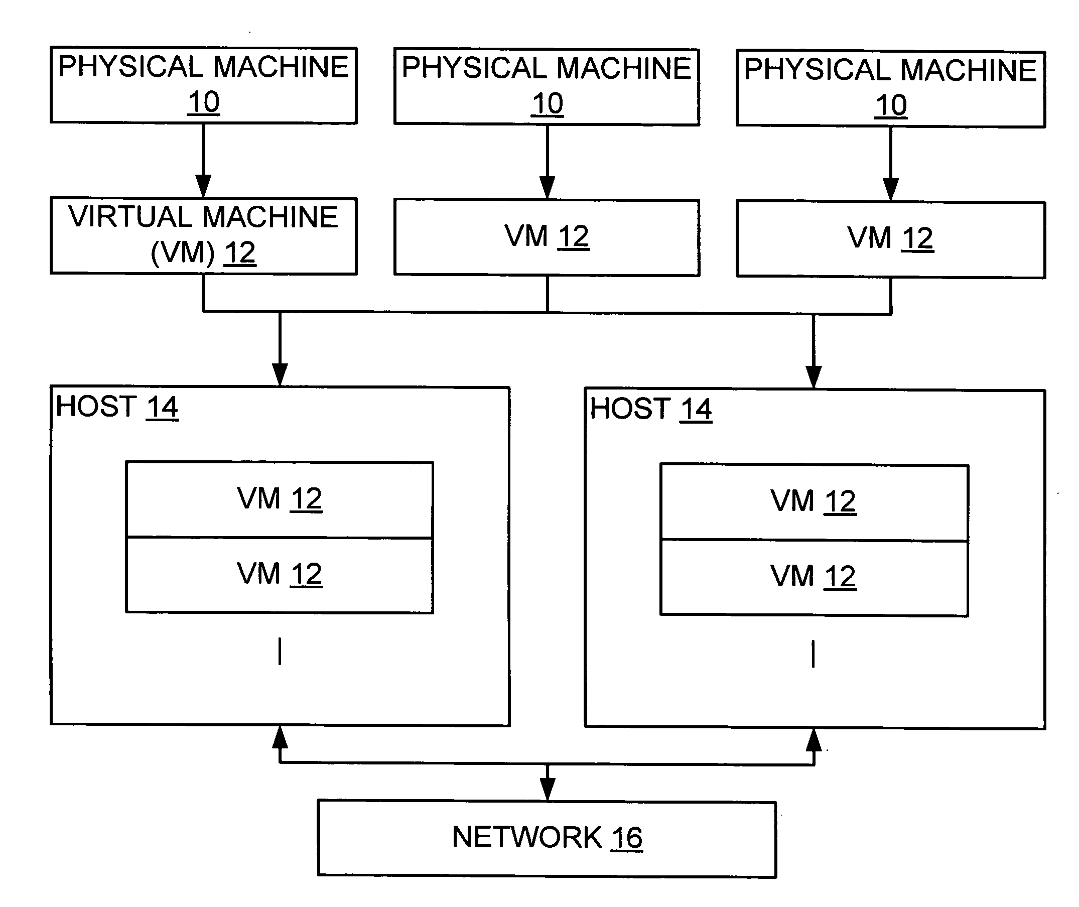
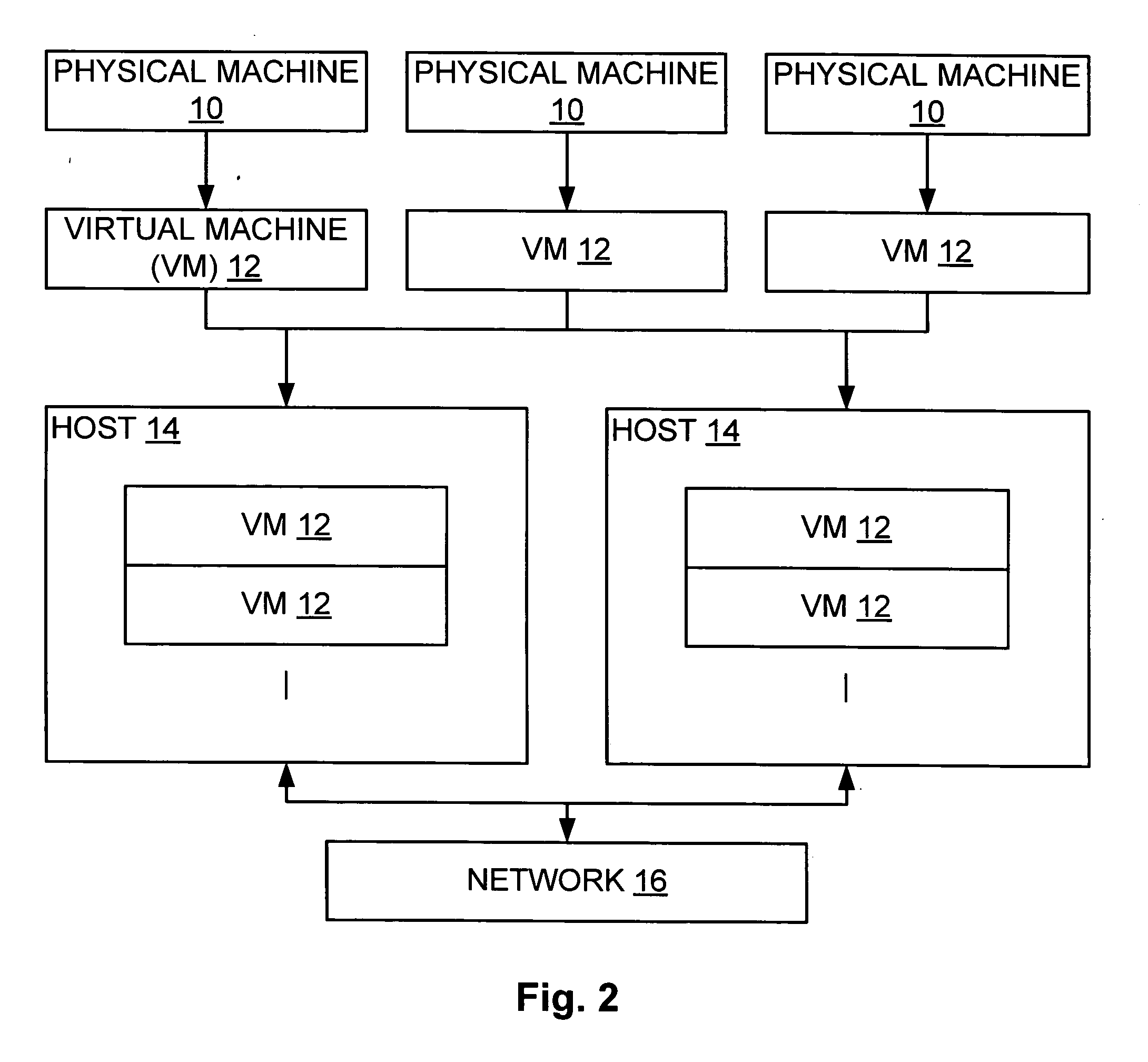
TECHNICAL FIELD[0001]The present invention relates to selecting a host for a virtual machine based on a characterization of the workload of each of a plurality of hosts as well as a characterization of the workload of the virtual machine. In a similar manner, the present invention relates to determining whether a physical machine should or could be virtualized as a virtual machine and deployed to a host, here based on a characterization of the workload of a typical host as well as a characterization of the workload of the physical machine.BACKGROUND OF THE INVENTION[0002]As should be appreciated, a virtual machine (‘VM’) is a software construct or the like operating on a computing device or the like (i.e., a ‘host’) for the purpose of emulating a hardware system. Typically, although not necessarily, the VM is an application or the like, and may be employed on the host to instantiate a use application or the like while at the same time isolating such use application from such host de...

Claims


Application Information

Patent Timeline
IPC IPC(8): G06F9/455
CPCG06F8/61G06F9/5005G06F9/455G06F9/45533
Inventor WAHLERT, BRIAN M.VEGA, RENE ANTONIOGIBSON, ROBERTFRIES, ROBERT M.SCHEIDEL, WILLIAM L.DOURNOV, PAVEL A.OSLAKE, JOHN MORGAN
Owner MICROSOFT TECH LICENSING LLC
Learn More