

Calibration device and method for a micro-thrust measurement system
A technique for measuring systems, calibrating devices, used in measuring devices, force/torque/work measuring instruments, instruments, etc.
Active Publication Date: 2014-01-22
LANZHOU INST OF PHYSICS CHINESE ACADEMY OF SPACE TECH
View PDF1 Cites 8 Cited by
- Summary
- Abstract
- Description
- Claims
- Application Information
AI Technical Summary
Problems solved by technology
Adopt in the measurement system that electric thruster is carried out micro-thrust measurement for the existing mode that adopts fork spring support
Method used
View moreImage
Smart ImageViewing Examples

Examples
Embodiment Construction
[0030] Below in conjunction with the accompanying drawings, the preferred embodiments of the present invention will be further described in detail.
[0042]
Login to View More PUM
 Abstract
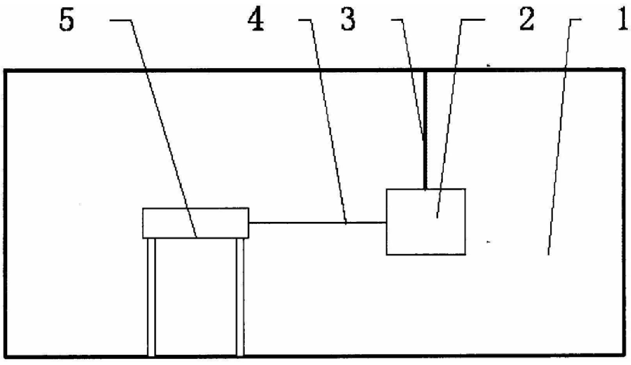
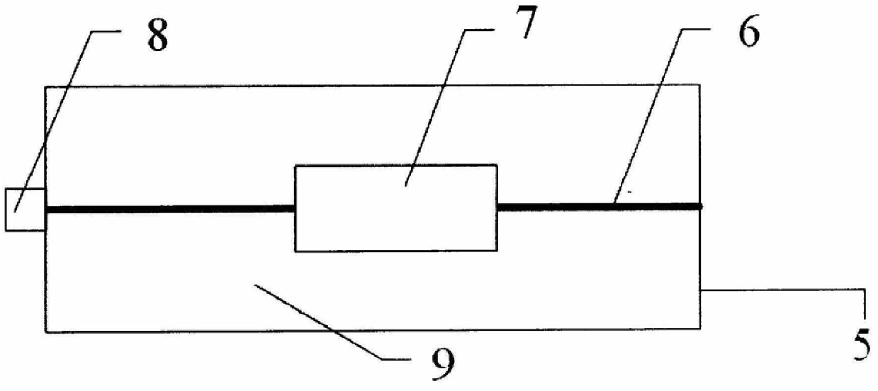
The invention relates to a calibration device and method for a micro-thrust measurement system, belonging to the technical field of micro-thrust measurement of electric thrusters. The calibration device is mainly composed of a thruster, elastic parts, filaments and a calibration system; the calibration system is mainly composed of a lead screw, an electronic tension gauge, a stepping motor and a platform; one end of the elastic part is hoisted in a vacuum environment, and the other end is connected to the thrust connected to the thruster, perpendicular to the transverse centerline of the thruster; one end of the thruster is connected to one end of the electronic tension gauge through a filament, and the straightening direction of the filament in the straightened state is consistent with the direction of the transverse centerline of the thruster; the stepping motor The lead screw is fixed on the platform, the stepper motor is connected with the lead screw, the axis direction of the lead screw is parallel to the straightening direction of the filament, the electronic tension gauge is fixed on the lead screw, and the stepper motor, electronic tension gauge and filament are arranged in sequence. The calibration accuracy of the calibration device does not require evaluation of the effects of friction; real-time calibration of the thrust measurement system is possible.
Description
A calibration device and method for a micro-thrust measurement system Technical field The present invention relates to a kind of calibration device and method of micro-thrust measurement system, belong to electric thruster micro-thrust measurement Quantitative technology field. Background technique The patent number is: ZL200610089041.8, and the disclosure date is: on February 21st, 2007, and the title is: "A kind of applicable In the Chinese patent "Thrust measurement system for micro-thrust engines in space", it is disclosed that the propeller is supported by a fork spring. The force device is used to measure the small thrust, and the measurement system is calibrated by a combination of weights and pulleys. this method Although the operation is convenient, its disadvantage is that the friction generated by the pulley cannot be effectively evaluated, so that the calibrated Availability has an impact; the measurement system cannot be calibrated in real time. Conte...
Claims
Login to View More Application Information
Patent Timeline
 IPC IPC(8): G01L5/00
Inventor田华兵顾左郭宁
OwnerLANZHOU INST OF PHYSICS CHINESE ACADEMY OF SPACE TECH