Method and device for calibrating sensor postures of robot in real time and terminal equipment

A sensor and robot technology, applied in the field of sensor control of industrial robots, can solve the problem of not being able to reflect the relationship between sensors and robots in real time

Inactive Publication Date: 2018-11-16
崧智智能科技(苏州)有限公司
View PDF6 Cites 5 Cited by
  • Summary
  • Abstract
  • Description
  • Claims
  • Application Information

AI Technical Summary

Problems solved by technology

[0004] The main purpose of the present invention is to propose a method, device and terminal equipment for real-time calibration of robot sensor posture, so as to solve the problem

Method used


Image

  • Method and device for calibrating sensor postures of robot in real time and terminal equipment
  • Method and device for calibrating sensor postures of robot in real time and terminal equipment
  • Method and device for calibrating sensor postures of robot in real time and terminal equipment

Examples


Embodiment 1

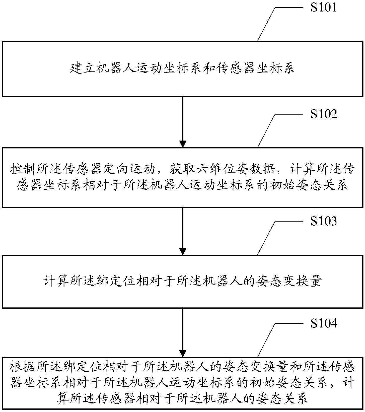
[0072] Such as figure 1 As shown, the embodiment of the present invention provides a method for real-time calibration of the posture of a robot sensor. The robot is provided with a binding position of the sensor, and the binding position can be located at any position of the robot, such as a robot end effector. , A robot image collector, etc., which are not specifically limited in the embodiment of the present invention; the sensor can be set in the binding position, and the method for real-time calibration of the robot sensor posture includes:

[0073] S101. Establish a robot motion coordinate system and a sensor coordinate system.

[0074] In the above step S101, the normal robot has its own motion coordinate system to determine the position and posture of the robot; and the sensor, as a signal input device, controls the cap by pushing, pulling, pressing, lifting, rotating and tilting. , Can generate data describing the position and attitude such as translation, pitch, roll and ...

Embodiment 2

[0129] Such as Figure 4 As shown, the embodiment of the present invention provides an apparatus 40 for real-time calibration of the posture of a robot sensor. The robot is provided with a binding position of the sensor, the sensor is arranged at the binding position, and the real-time calibration robot The sensor attitude device 40 includes:

[0130] The coordinate system establishment module 41 is used to establish the robot motion coordinate system and the sensor coordinate system.

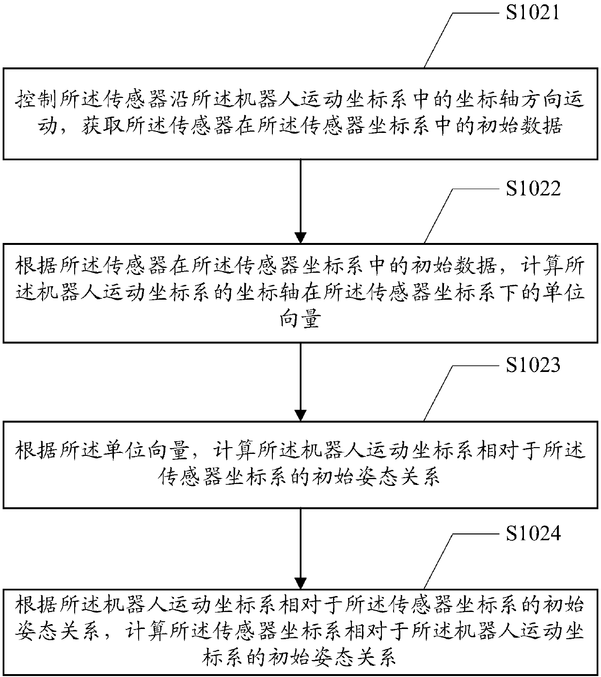
[0131] The first calculation module 42 is configured to control the directional movement of the sensor, obtain six-dimensional pose data, and calculate the initial posture relationship of the sensor coordinate system relative to the robot motion coordinate system.

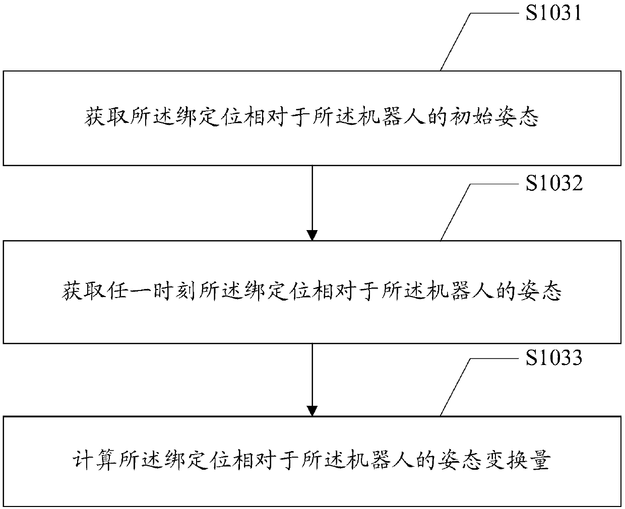
[0132] The second calculation module 43 is configured to calculate the posture transformation amount of the binding position relative to the robot.

[0133] The third calculation module 44 is configured to calculate the sensor relative to t...


PUM


Abstract

The invention is applied to the technical fields of sensing control of industrial robots, and provides a method and device for calibrating sensor postures of a robot in real time and terminal equipment. A binding position of a sensor is arranged on the robot; and the sensor is arranged on the binding position. The method for calibrating sensor postures of the robot comprises the following steps: building a robot motion coordinate system and a sensor coordinate system; controlling orientated motion of the sensor; acquiring six-dimensional posture data; calculating an initial posture relation ofthe sensor coordinate system relative to the robot motion coordinate system; calculating posture converted quantity of the binding position relative to the robot; and calculating the posture relationof the sensor relative to the robot according to the posture converted quantity of the binding position relative to the robot and the initial posture relation of the sensor coordinate system relativeto the robot motion coordinate system. According to the method and device for calibrating sensor postures of the robot in real time disclosed by the invention, the phenomenon that control errors caused by the change of the sensor postures during control of the positions and the postures of the robot is avoided.

Description

Technical field [0001] The invention relates to the technical field of industrial robot sensor control, in particular to a method, a device and terminal equipment for calibrating the attitude of a robot sensor in real time. Background technique [0002] Sensing and measurement are an important part of the control system, and the most widely used multi-dimensional force sensor is the six-dimensional force sensor. The generalized six-dimensional force sensor can check the three-dimensional orthogonal force and three-dimensional orthogonal torque in any force system in space. Due to its rich force measurement information and high measurement accuracy, it is mainly used in force and force-position control situations, such as the end of a robot Actuator, wheel force detection during automobile driving, contour tracking, precision assembly, hand coordination, etc. As a signal input device, the six-dimensional sensor can generate signals describing position and attitude such as transla...

Claims


Application Information

Patent Timeline
IPC IPC(8): B25J9/16B25J19/00G01C21/00
CPCB25J9/1605B25J9/1671B25J19/0095G01C21/00
Inventor 黄渭刘志龙陈晨杨薛鹏王佩闯
Owner 崧智智能科技(苏州)有限公司
Why Eureka
Try Eureka