Spraying machine for plant protection

A technology for machinery and plant protection, which is applied in the device, application, animal husbandry and other directions of catching or killing insects. Complete, good effect, simple structure effect

Inactive Publication Date: 2017-09-22
合肥市老海新材料有限公司
View PDF7 Cites 3 Cited by
  • Summary
  • Abstract
  • Description
  • Claims
  • Application Information

AI Technical Summary

Problems solved by technology

[0002] The traditional plant protection machinery is an integral structure, and there are two main ways of working: the first is that the vehicle walks on a fixed road, and the spray boom is extended to the farmland for operation. Therefore, the longer the spray boom, the longer the spray The larger the structure of the pole, the larger the plant protection machinery used in this way is often huge in size and high in cost; the second is that the whole machine reciprocates in the farmland for spraying operations. This method mainly has the following disadvantages: 1. In the farmland When walking and working, damage to crops is inevitable; 2. For paddy fields or swampy land, it is difficult for ordinary plant protection machinery to walk smoothly; 3. Due to the limited liquid medicine and power it carries, the battery life is poor, and the area of ​​one operation is small.
Adopting this structure can solve the above-mentioned unsatisfactory spraying effect to a certain extent. However, when the plant protection machine contains multiple nozzles, the fans rotate in the same direction, so that the wind force tends to be equal at the intersection of the two fans. In the opposite direction, the wind force is weakened or even offset, leaving a blind spot for stirring, and the effect is still not ideal

Method used


Image

  • Spraying machine for plant protection
  • Spraying machine for plant protection
  • Spraying machine for plant protection

Examples


Embodiment 1

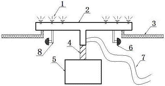
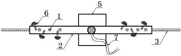
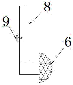
[0025] A plant protection machine for spraying, comprising a spray boom 2, a motor 5, a fan 6 and a hose 7, the spray boom 2 is in the shape of a "T", the spray boom 1 is a sealed hollow rod, and the spray boom 2 is grafted on the rotating shaft 4 of the motor 5 , the rotating shaft 4 extends from the inside of the motor 5, the rotating shaft 4 periodically changes the direction of rotation, the fan 6 is installed under the spray bar 2, and the fan 6 blows air along the horizontal divergent direction of the spray bar 1 rotation, and the connecting rod 8 of the fan 6 is a telescopic rod , the connecting rod 8 is provided with a screw fastener 9, the hose 7 is connected and communicated with the spray rod 2, the hose 7 is connected to the lower end of the vertical part of the "T"-shaped spray rod 2, and a spray head is arranged above the spray rod 2 1. Nozzle 1 is distributed at both ends of spray bar 2.

[0026] There are at least two fans 6 on the spray bar 2. When the number ...

Embodiment 2

[0033] A plant protection machine for spraying, comprising a spray boom 2, a motor 5, a fan 6 and a hose 7, the spray boom 2 is in the shape of a "T", the spray boom 1 is a sealed hollow rod, and the spray boom 2 is grafted on the rotating shaft 4 of the motor 5 , the rotating shaft 4 extends from the inside of the motor 5, the rotating shaft 4 periodically changes the direction of rotation, the fan 6 is installed under the spray bar 2, and the fan 6 blows air along the horizontal divergent direction of the spray bar 1 rotation, and the connecting rod 8 of the fan 6 is a telescopic rod , the connecting rod 8 is provided with a screw fastener 9, the hose 7 is connected and communicated with the spray rod 2, the hose 7 is connected to the lower end of the vertical part of the "T"-shaped spray rod 2, and a spray head is arranged above the spray rod 2 1. Nozzle 1 is distributed at both ends of spray bar 2.

[0034] The spray boom 2 is made of aluminum alloy material, which can gre...

Embodiment 3

[0041] A plant protection machine for spraying, comprising a spray boom 2, a motor 5, a fan 6 and a hose 7, the spray boom 2 is in the shape of a "T", the spray boom 1 is a sealed hollow rod, and the spray boom 2 is grafted on the rotating shaft 4 of the motor 5 , the rotating shaft 4 extends from the inside of the motor 5, the rotating shaft 4 periodically changes the direction of rotation, the fan 6 is installed under the spray bar 2, and the fan 6 blows air along the horizontal divergent direction of the spray bar 1 rotation, and the connecting rod 8 of the fan 6 is a telescopic rod , the connecting rod 8 is provided with a screw fastener 9, the hose 7 is connected and communicated with the spray rod 2, the hose 7 is connected to the lower end of the vertical part of the "T"-shaped spray rod 2, and a spray head is arranged above the spray rod 2 1. Nozzle 1 is distributed at both ends of spray bar 2.

[0042] The spray boom 2 is made of aluminum alloy material, which can gre...


PUM


Abstract

The invention provides a spraying machine for plant protection. The equipment comprises a spraying rod, a motor, a fan and a hose, wherein the spraying rod is T-shaped; the spraying rod is a sealed hollow rod; the spraying rod is grafted on a spindle of the motor; the spindle extends out from the motor; the rotation direction of the spindle is converted periodically; the fan is installed under the spraying rod; the fan blows wind along a horizontal divergence direction of rotation of the spraying rod; a connecting rod of the fan is a telescopic rod; a screw fastening part is disposed on the connecting rod; the hose is connected to and communicates with the spraying rod; the hose is connected to the lower end of the vertical part of the T-shaped spraying rod; and spraying nozzles are disposed on the spraying rod and distributed on two ends of the spraying rod. According to the invention, the structure is simple; the cost is low; spraying orientations are complete; effects are good; spraying efficiency is greatly increased; and thus energy consumption in spraying is reduced, and use cost is reduced.

Description

technical field [0001] The invention belongs to the technical field, and in particular relates to a spraying plant protection machine. Background technique [0002] The traditional plant protection machinery is an integral structure, and there are two main ways of working: the first is that the vehicle walks on a fixed road, and the spray boom is extended to the farmland for operation. Therefore, the longer the spray boom, the longer the spray The larger the structure of the pole, the larger the plant protection machinery used in this way is often huge in size and high in cost; the second is that the whole machine reciprocates in the farmland for spraying operations. This method mainly has the following disadvantages: 1. In the farmland When walking, damage to crops is inevitable; 2. For paddy fields or swampy land, it is difficult for ordinary plant protection machinery to walk smoothly; 3. Due to the limited liquid medicine and power it carries, the battery life is poor, a...

Claims


Application Information

Patent Timeline
Patent Type & Authority Applications(China)
IPC IPC(8): A01M7/00
CPCA01M7/0028A01M7/0053
Inventor 牛淑美
Owner 合肥市老海新材料有限公司
Why Eureka
Try Eureka