Self-locking slider with double horse hooks

A horse hook and self-locking technology, applied in the field of zipper heads, can solve the problems of shortening the service life of the self-locking zipper head, automatic sliding and self-locking, poor self-locking function, etc., achieving good self-locking effect, firm and reliable self-locking, and improved The effect of service life

Active Publication Date: 2020-05-19
FUJIAN SBS ZIPPER SCI & TECH CO LTD
View PDF5 Cites 1 Cited by
  • Summary
  • Abstract
  • Description
  • Claims
  • Application Information

AI Technical Summary

Problems solved by technology

[0003] The traditional self-locking slider, because there is only one shrapnel and a hook inside the self-locking slider, so after a period of use, once the shrapnel or the hook is damaged, it is prone to poor self-locking or self-locking failure, and self-locking occurs. The slider automatically slides down on the zipper or the self-locking is not up to standard, and the self-locking function is poor; in addition, it will also shorten the service life of the self-locking zipper head

Method used


Image

  • Self-locking slider with double horse hooks
  • Self-locking slider with double horse hooks
  • Self-locking slider with double horse hooks

Examples


Embodiment 1

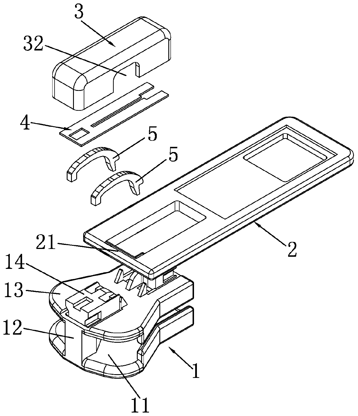
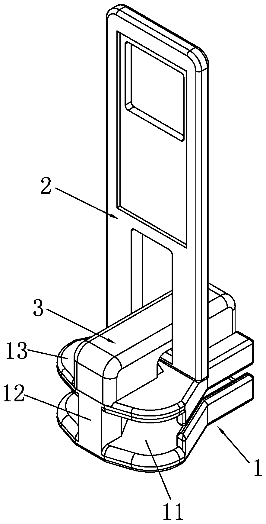
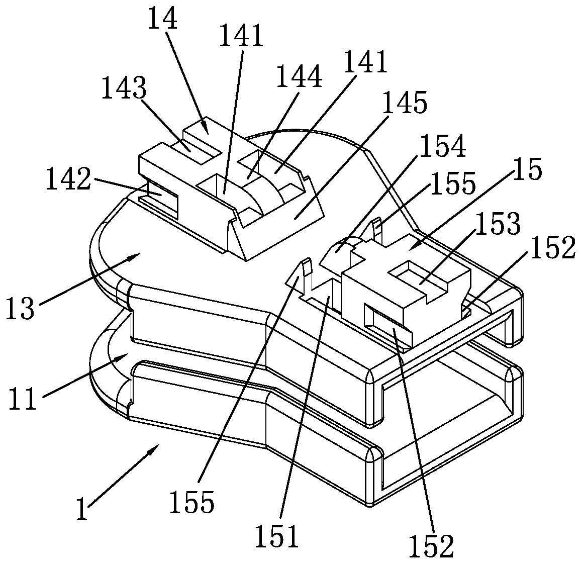
[0023] like Figure 1 to Figure 7 As shown, a self-locking slider with double horse hooks includes a slider body 1, a pull tab 2, a cap 3, an elastic sheet 4 and two horse hooks 5. The slider body 1 consists of a lower wing plate 11, a guide post 12 is connected with the upper wing plate 13, the front end of the top surface of the upper wing plate 13 is provided with a front mounting portion 14, the rear end of the top surface of the upper wing plate 13 is provided with a rear mounting portion 15, and the pivot 21 of the pull tab 2 is provided at the front Between the mounting portion 14 and the rear mounting portion 15 , the cap 3 , the elastic pieces 4 and the two horse hooks 5 are installed on the front mounting portion 14 and the rear mounting portion 15 , so that the elastic pieces 4 press the tops of the two horse hooks 5 .

[0024] like Figure 1 to Figure 3 As shown, the front mounting portion 14 is provided with two first mounting holes 141 for assembling the horse h...

Embodiment 2

[0030] like Figure 8 and Figure 9As shown, on the basis of Embodiment 1, the groove positioning structures on the tops of the front mounting portion 14 and the rear pressing mounting portion 15 of the slider body 1 are set as upwardly protruding positioning structures, specifically: the front mounting portion The top of the 14 is provided with a first positioning protrusion 146, and the top of the rear mounting portion 15 is provided with a second positioning protrusion 156. The first positioning protrusion 146 and the second positioning protrusion 156 have the same structure, and both are square protrusions. The inside of the cap 3 does not need to be provided with positioning structures corresponding to the first positioning bumps 146 and the second positioning bumps 156 . The assembly process of the self-locking slider of Example 2 is basically the same as that of the self-locking slider of Example 1. The only difference is that in Example 1, the elastic sheet 4 is first...


PUM


Abstract

The invention provides a self-locking puller with double horse hooks. The self-locking puller comprises a puller body, a pulling sheet, a cap, an elastic sheet, and two horse hooks, the puller body is constituted by making a lower wing plate, a guide pillar and an upper wing plate connected, a front installation part and a rear installation part are arranged at the top surface of the upper wing plate, two first installation holes are formed in the front installation part, and two second installation holes are formed in the rear installation part; first connecting clamping grooves are formed in both the left side wall and the right side wall of the front mounting part, and second connecting clamping grooves are formed in both the left side wall and the right side wall of the rear mounting part; a first positioning groove is formed in the top of the front installation part, and a second positioning groove is formed in the top of the rear installation part; an opening groove is formed in the middle of the elastic sheet, and the elastic sheet is separated into a left elastic sheet and a right elastic sheet, and the left elastic sheet and the right elastic sheet are symmetrically arranged; loading lugs are arranged at the top end of the inside of the cap. In the elastic sheet of the self-locking puller, two mutually independent elastic parts are arranged to correspond to the two horse hooks, when the left elastic sheet and the right elastic sheet apply acting force to the corresponding horse hooks to achieve self-locking of the puller, the left elastic sheet and the right elastic sheet are not interfered mutually, and thus the self-locking function of the puller is sharply promoted.

Description

technical field [0001] The invention relates to a zipper slider, in particular to a self-locking slider with double horse hooks. Background technique [0002] At present, the traditional self-locking sliders on the market often have a shrapnel and a horse hook inside the self-locking slider, and its self-locking function often relies on the horse hook and the shrapnel installed on the slider body to realize the slider. Self-locking; the top of the horse hook is subjected to the pressure of the shrapnel, so that the free end of the horse hook is stuck with the zipper teeth to realize the self-locking of the slider; , the free end of the horse hook is separated from the zipper teeth to realize the unlocking of the slider, and the self-locking slider can be moved. [0003] The traditional self-locking slider has only one shrapnel and one horse hook inside the self-locking slider, so after a period of use, once the shrapnel or the hook is damaged, it is easy to have poor self-l...

Claims


Application Information

Patent Timeline
Patent Type & Authority Patents(China)
IPC IPC(8): A44B19/30
CPCA44B19/306
Inventor 周海辉朱松峰张田
Owner FUJIAN SBS ZIPPER SCI & TECH CO LTD
Why Eureka
Try Eureka