
Pneumatic cutter adjusting mechanism

A pneumatic adjustment and cylinder technology, applied in the field of compound machines, can solve the problems of low degree of automation, inability to lift and lower the cutter mechanism, and difficulty in achieving the effect of trimming, so as to achieve the effect of optimizing the effect of trimming.

Inactive Publication Date: 2017-09-22
JIANGSU HONGHUA SPECIAL EQUIP CO LTD
View PDF0 Cites 1 Cited by
  • Summary
  • Abstract
  • Description
  • Claims
  • Application Information

AI Technical Summary

Problems solved by technology

However, the existing composite machines all adopt a manually adjusted cutter mechanism, which is adjusted by rotating the hand wheel to drive the screw to drive the cutter mechanism to move, and the degree of automation is low.
In addition, the cutter mechanism of the existing compound machine cannot be lifted up and down, and the feed rate cannot be adjusted. It is difficult to achieve the optimal edge trimming effect for different products.

Method used


Image

  • Pneumatic cutter adjusting mechanism
  • Pneumatic cutter adjusting mechanism
  • Pneumatic cutter adjusting mechanism

Examples


Embodiment Construction

[0014] The following will clearly and completely describe the technical solutions in the embodiments of the present invention with reference to the accompanying drawings in the embodiments of the present invention. Obviously, the described embodiments are only some, not all, embodiments of the present invention. Based on the embodiments of the present invention, all other embodiments obtained by persons of ordinary skill in the art without making creative efforts belong to the protection scope of the present invention.

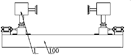
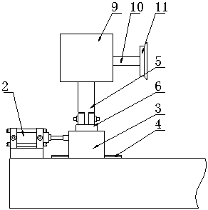
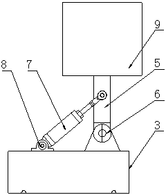
[0015] see Figure 1-3 , in the embodiment of the present invention, the pneumatic knife adjustment mechanism includes a pneumatic adjustment mechanism 1, the pneumatic adjustment mechanism 1 includes a size adjustment mechanism, a feed adjustment mechanism and a cutter mechanism, and the size adjustment mechanism includes a first cylinder 2, a second One sliding seat 3 and the first slide rail 4, the first sliding seat 3 is installed on the first sliding rail...


PUM


Abstract

The invention discloses a pneumatic knife adjustment mechanism, which includes a pneumatic adjustment mechanism. The pneumatic adjustment mechanism includes a size adjustment mechanism, a feed adjustment mechanism and a knife cutter mechanism. The size adjustment mechanism includes a first cylinder, a first sliding seat and a first Slide rail, the first slide seat is installed on the first slide rail through the slider, the first slide rail is installed on the machine base, the outside of the first slide seat is connected to the telescopic rod of the first cylinder, and the first cylinder is fixed on the machine base The feed adjustment mechanism includes a swing arm, a swivel seat and a second cylinder, the lower end of the swing arm is connected to the swivel seat, the swivel seat is fixed on the first sliding seat, the middle part of the swing arm is hinged with the piston rod of the second cylinder, and the second cylinder The bottom of the swing arm is installed on the first sliding seat through the rotating cylinder seat; the cutter mechanism is installed on the top of the swing arm. The cutter mechanism includes a casing, a cutter shaft and a cutter blade. The cutter blade is installed on the cutter shaft. The coupling is connected to the output shaft of the cutter motor in the casing; the pneumatic knife adjustment mechanism automatically adjusts the horizontal and vertical positions of the cutter through the cylinder, can adjust the feed rate, and optimize the trimming effect, which is worthy of vigorous promotion.

Description

technical field [0001] The invention relates to the technical field of composite machines, in particular to a pneumatic knife adjustment mechanism. Background technique [0002] In the processing process of the composite machine, in order to improve the quality of the finished product, it is usually equipped with a trimming process. For the trimming of composite products of different sizes, the cutter needs to be adjusted to achieve size adaptation. However, the existing composite machines all adopt a manually adjusted cutter mechanism, which is adjusted by rotating the hand wheel to drive the screw to drive the cutter mechanism to move, and the degree of automation is low. In addition, the cutter mechanism of the existing composite machine cannot be raised and lowered, and the feed rate cannot be adjusted, so it is difficult to achieve the best edge trimming effect for different products. Contents of the invention [0003] The present invention aims to provide a pneumati...

Claims


Application Information

Patent Timeline
Patent Type & Authority Applications(China)
IPC IPC(8): B26D7/26
CPCB26D7/2628B26D2007/2664
Inventor 朱加前
Owner JIANGSU HONGHUA SPECIAL EQUIP CO LTD
Learn More