
Pipe conveying device

A pipeline transportation and pipeline technology, which is applied in the field of pipeline transportation devices, can solve problems such as easy to be stained with dust, the dust of the installer falls in other places, and affects the environment

Active Publication Date: 2017-09-22
重庆市永川区植成家俱厂
View PDF5 Cites 17 Cited by
  • Summary
  • Abstract
  • Description
  • Claims
  • Application Information

AI Technical Summary

Problems solved by technology

[0004] The prior art also has the following problems: 1. The pipes are easily stained with dust when they are placed on the storage rack, and the pipe surface is not dedusted during the process of taking and delivering the pipes. When using these pipes with dust on the surface, it will not only make the installers The body will be stained with dust, and it is easy for the dust to enter the air and finally fall elsewhere, affecting the environment; 2. When removing the pipe from the holding part, it is very inconvenient to manually remove the pipe from the holding part

Method used


Image

  • Pipe conveying device
  • Pipe conveying device
  • Pipe conveying device

Examples


Embodiment Construction

[0029] The present invention will be described in further detail below by means of specific embodiments:

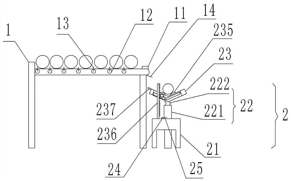
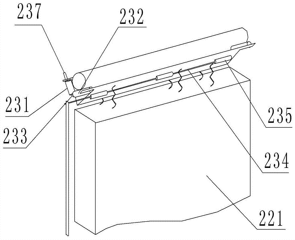
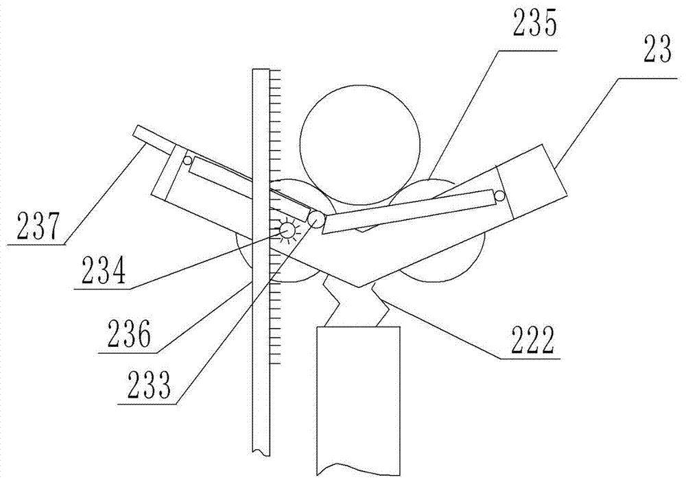
[0030] The reference signs in the drawings of the description include: storage rack 1, rubber protrusion 11, toggle shaft 12, paddle 13, switch 14, pick-up mechanism 2, support platform 21, support seat 22, seat body 221, spring 222, pick and place part 23, short roller 231, long roller 232, magnet 233, rotating shaft 234, dust removal roller 235, first rack 236, dial bar 237, groove 238, sliding hole 239, first electromagnet 24, the first Two electromagnets 25.

[0031] Such as figure 1 , figure 2 and image 3 As shown, the pipeline conveying device includes a storage rack 1, the left side of the storage rack 1 is fixedly connected with a baffle to prevent the pipeline from falling, and the right side of the storage rack 1 is fixedly connected with a rubber protrusion 11. The storage rack 1 is provided with a toggle portion that can toggle the pipeline. The togglin...


PUM


Abstract

The invention relates to the technical field of pipe conveying, in particular to a pipe conveying device. The pipe conveying device comprises a storage rack and a taking and feeding mechanism, wherein a shifting part capable of shifting pipes is arranged on the storage rack; the taking and feeding mechanism comprises a supporting table and a supporting seat which is driven by a hydraulic cylinder and penetrates through the supporting table; a V-shaped taking and placing part is arranged at the upper end of the supporting seat; V-shaped rollers which can be in contact with the pipes are respectively arranged at two ends of the taking and placing part; each V-shaped roller comprises a short roller and a long roller which are hinged to each other; a magnet is arranged at a position where each short roller is hinged to the corresponding long roller; each position where the corresponding short roller is hinged to the corresponding long roller and the lowest position of the taking and placing part are not positioned on the same straight line; the taking and placing part is provided with a rotating shaft, a shaft cavity and dust-removing rollers; the dust-removing rollers are driven by the rotating shaft; a first gear is arranged at one end of the rotating shaft; the shaft cavity is positioned in the side wall of the taking and placing part; a first rack which can be engaged with the first gear is arranged on the supporting table; and an electromagnet is further arranged on the supporting table. By the scheme, dust on the surfaces of the pipes can be removed in a conveying process, and furthermore, the pipes can be taken down from the conveying device conveniently.

Description

technical field [0001] The invention relates to the technical field of pipeline transportation, in particular to a pipeline transportation device. Background technique [0002] The traditional material storage rack often exists as an independent body, and its function is only to store pipelines (such as steel pipes, iron pipes, etc.). Manual handling is generally used for the delivery of pipelines, which is time-consuming, laborious, and inefficient. The traditional material storage rack lacks a corresponding device that cooperates with the delivery pipeline to realize the automatic delivery pipeline device. [0003] In order to solve the above problems, the pipe pick-up and delivery device used in the prior art includes a base, and a hydraulic cylinder is arranged inside the base. department. When in use, push the pick-up device to the required position, the support seat moves upward after the hydraulic cylinder is powered on, and when the holding part moves to the positi...

Claims


Application Information

Patent Timeline
Patent Type & Authority Applications(China)
IPC IPC(8): B65G47/74B65G47/82B08B9/023
CPCB08B9/023B65G47/74B65G47/82
Inventor 李天能
Owner 重庆市永川区植成家俱厂
Learn More