A pneumatic ship unloader

A ship unloader and pneumatic technology, applied in the direction of conveyor, loading/unloading, conveying bulk materials, etc., can solve the problem that the suction pipe cannot be vertically downward, affect the suction effect, and affect the angle of the suction pipe, etc. Friction and wear problem, solve wear problem, good sealing effect

Active Publication Date: 2019-09-20
NANTONG RAINBOW HEAVY MACHINERIES
View PDF5 Cites 0 Cited by
  • Summary
  • Abstract
  • Description
  • Claims
  • Application Information

AI Technical Summary

Problems solved by technology

[0003] Due to the uncertainty of the berthing position of the ship and the position of the ship's warehouse, it is necessary to adjust the position of the suction pipe when unloading the ship, that is, it is necessary to adjust the pitch angle of the arm of the ship unloader or the front and rear positions of the suction pipe. It will affect the angle of the suction pipe so that the suction pipe cannot be vertically downward and affect the suction effect

Method used


Image

  • A pneumatic ship unloader
  • A pneumatic ship unloader
  • A pneumatic ship unloader

Examples


Embodiment Construction

[0025] The present invention will be further described in detail below in conjunction with the accompanying drawings and examples. The following examples are explanations of the present invention and the present invention is not limited to the following examples.

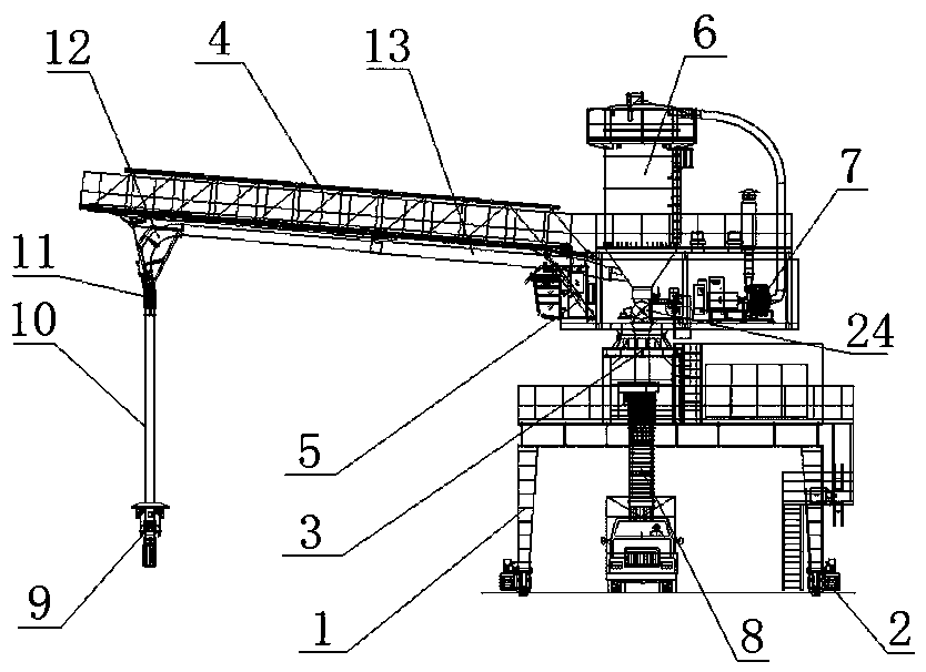
[0026] Such as figure 1 As shown, a pneumatic ship unloader of the present invention includes a gantry 1, a traveling mechanism 2, a rotating platform 3, an arm frame 4, a suction pipe, a luffing hydraulic cylinder 5, a dust removal cylinder 6, a fan 7 and a telescopic chute 8. The traveling mechanism 2 is set on the lower side of the mast 1, the rotating platform 3 is set on the upper end of the mast 1, one end of the boom 4 is hinged on the rotating platform 3, and one end of the luffing hydraulic cylinder 5 is hinged on the lower side of the boom 4. The other end of the width hydraulic cylinder 5 is hinged on the rotating platform 3, the suction pipe is arranged along the boom 4 and one end of the suction pipe is...


PUM


Abstract

Disclosed is a pneumatic ship unloader comprising a portal frame (1), a travelling mechanism (2), a rotating platform (3), an arm frame (4), a material suction pipeline, a variable amplitude hydraulic cylinder (5), a dedusting cylinder (6), a fan (7) and a telescopic slip cylinder (8), wherein the material suction pipeline comprises a material suction nozzle (9), a vertical pipeline (10), a metal hose (11), a bend (12) and a telescopic sleeve pipe (13), wherein the metal hose (11) is formed by a plurality of taper cylinders connected end to end, and each taper cylinder is configured to have a smaller bottom surface of the lower end than that of the upper end, and for every two adjacent taper cylinders, the upper end of the lower taper cylinder is sleeved on the outer side of the lower end of the uper taper cylinder, and both sides of each taper cylinder are proved with connecting parts (14) and the connecting parts (14) of adjacent taper cylinders are hinged to each other, and the outer side of connecting portions of adjacent taper cylinders is sealed by a rubber belt (15), and the rubber belt (15) is fixed to the taper cylinder through a clamp (16). The material suction pipeline can automatically adjust the angle to ensure perpendicularity by providing the metal hose (11) in the material suction pipeline and ensuring the air impermeability of the pipeline through a specific hose structure.

Description

technical field [0001] The invention relates to a ship unloader, in particular to a pneumatic ship unloader. Background technique [0002] The pneumatic ship unloader is a ship unloading machine that uses the negative pressure flow formed by the fan in the pipeline to suck and unload bulk materials from the cabin. Although the machine consumes a lot of energy, has certain requirements for the materials to be sent (particle size, viscosity, humidity), and has some shortcomings such as high working noise, it has simple structure, low cost, convenient operation, and good working conditions for workers; it is easy to realize Automatic control and management, strong adaptability to various ships, small cleaning volume, etc., are widely used in joint materials. Pneumatic ship unloader adopts pneumatic suction to unload bulk cargo. It is also a continuous bulk cargo unloader. It is mainly used for bulk grain unloading operations, and also for bulk cargo unloading operations such a...

Claims


Application Information

Patent Timeline
Patent Type & Authority Patents(China)
IPC IPC(8): B65G67/60B65G53/04B65G53/52
Inventor 崔益华葛磊闫伟红
Owner NANTONG RAINBOW HEAVY MACHINERIES
Why Eureka
Try Eureka