
A main and auxiliary cavity type garbage jam prevention device for electric sweeper

A sub-cavity and anti-jamming technology, applied in cleaning methods, road cleaning, construction, etc., can solve the problems of increased instantaneous power of conveying motors, reduced operating efficiency, hidden safety hazards, etc., to reduce quality, improve life, and solve blockage problems. Effect

Active Publication Date: 2019-05-10
TAIYUAN UNIVERSITY OF SCIENCE AND TECHNOLOGY
View PDF8 Cites 0 Cited by
  • Summary
  • Abstract
  • Description
  • Claims
  • Application Information

AI Technical Summary

Problems solved by technology

[0002] The problems existing in the cleaning process of the road sweeper are: for the suction sweeper, some flexible and strip-shaped garbage (such as branches, plastic bags, etc.) are blocked in the dust suction pipeline during the cleaning process, causing the suction fan to In overload work, it is necessary for the cleaning truck operator to stop and manually dredge the dust suction pipeline
[0003] For some cleaning vehicles equipped with conveying devices (such as belt conveying devices), strips and flexible garbage will be stuck at the mouth of the conveying channel or inside the conveying channel. In most cases, manual dredging is required, resulting in poor operating efficiency If it is seriously stuck, the instantaneous power of the conveying motor will increase, causing potential safety hazards

Method used


Image

  • A main and auxiliary cavity type garbage jam prevention device for electric sweeper
  • A main and auxiliary cavity type garbage jam prevention device for electric sweeper
  • A main and auxiliary cavity type garbage jam prevention device for electric sweeper

Examples


Embodiment Construction

[0015] Preferred embodiments of the present invention will be described in detail below in conjunction with the accompanying drawings.

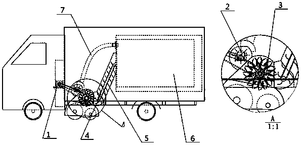
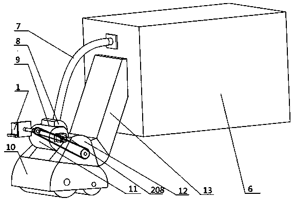
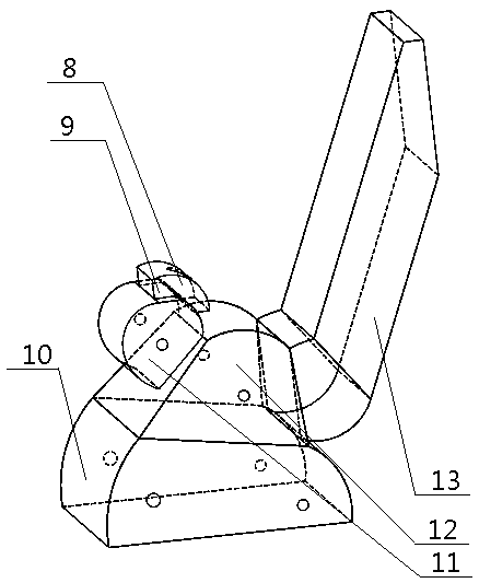
[0016] In the embodiment of the present invention such as figure 2 , 3 , 5. The present invention relates to an anti-jamming device for main and auxiliary chambers of electric cleaning vehicles, which includes a cavity installed on the vehicle frame. The cavity includes a main cavity, and an anti-seize guide wheel 3 is installed in the main cavity. 3 includes three impellers 303 on the left, middle and right, the impeller 303 is installed on the impeller shaft, the impeller shaft 302 of the left end impeller and the impeller shaft 311 of the right end impeller are respectively installed on the main cavity, and the impeller 303 is equipped with conveying blades 305, 308 The opening of the lower cavity 10 of the main cavity is equipped with two roller brushes; the openings at the left and right ends of the main cavity are also connected with ...


PUM


Abstract

The invention relates to a main-auxiliary cavity type garbage jamming prevention device of an electric sweeper truck. The main-auxiliary cavity type garbage jamming prevention device comprises cavities formed in a frame, wherein the cavities include a main cavity, a jamming prevention guide wheel is installed in a main cavity body and comprises a left impeller, a middle impeller and a right impeller, the impellers are installed on impeller shafts, the impeller shaft of the left impeller and the impeller shaft of the right impeller are respectively installed on the main cavity body, and conveying blades are installed on the impellers. The left end and the right end of the main cavity are opened and are also communicated with two auxiliary cavities, a screen guiding wheel is installed in the left-side auxiliary cavity and is installed on a screen guiding wheel impeller shaft, two ends of the screen guiding wheel impeller shaft are installed on the auxiliary cavity on the left side, and screen blades are installed on the screen guiding wheel. The main-auxiliary cavity type garbage jamming prevention device utilizes the jamming prevention guide wheel installed in the main cavity to cut, transport and guide garbage and meanwhile utilizes the screen guiding wheel in the left-side auxiliary cavity to convey the garbage and filter dust. The problem that strip-shaped flexible garbage blocks a garbage channel in the garbage sweeping process can be solved.

Description

technical field [0001] The invention belongs to the field of road cleaning equipment, and relates to an anti-jamming device for garbage in the main and auxiliary chambers of electric cleaning vehicles. Background technique [0002] The problems existing in the cleaning process of the road sweeper are: for the suction sweeper, some flexible and strip-shaped garbage (such as branches, plastic bags, etc.) are blocked in the dust suction pipeline during the cleaning process, causing the suction fan to In overload work, it is necessary for the cleaning truck operator to stop and manually dredge the dust suction pipeline. [0003] For some cleaning vehicles equipped with conveying devices (such as belt conveying devices), strips and flexible garbage will be stuck at the mouth of the conveying channel or inside the conveying channel. In most cases, manual dredging is required, resulting in poor operating efficiency If it is seriously stuck, the instantaneous power of the conveying...

Claims


Application Information

Patent Timeline
Patent Type & Authority Patents(China)
IPC IPC(8): E01H1/04
CPCE01H1/042E01H1/047
Inventor 赵富强黄庆学董竞朱壮壮张君王正谊
Owner TAIYUAN UNIVERSITY OF SCIENCE AND TECHNOLOGY
Learn More