Flow discarding and flow diversion device of rainwater down pipe and flow discarding and flow diversion method

A technology of diverting device and rain fall, applied in water supply device, sewage removal, waterway system, etc., can solve the problems of inconvenient installation and device maintenance, limited installation location, large device volume, etc. Low manufacturing cost and small size effect

Pending Publication Date: 2017-09-22
SICHUAN MUYU ENVIRONMENTAL PROTECTION TECH CO LTD
View PDF7 Cites 8 Cited by
  • Summary
  • Abstract
  • Description
  • Claims
  • Application Information

AI Technical Summary

Problems solved by technology

[0004] At present, the collection and disposal devices for rainwater drainage in cities have obvious limitations in practical application due to the large size of the device, high cost, limited installation location, and inconvenient installation and maintenance of the device.

Method used


Image

  • Flow discarding and flow diversion device of rainwater down pipe and flow discarding and flow diversion method
  • Flow discarding and flow diversion device of rainwater down pipe and flow discarding and flow diversion method
  • Flow discarding and flow diversion device of rainwater down pipe and flow discarding and flow diversion method

Examples


Embodiment 1

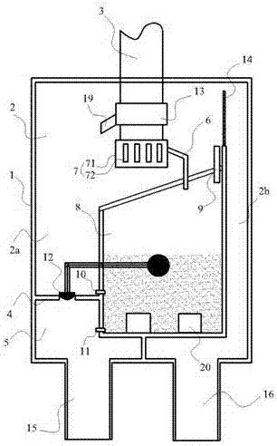
[0042] Rain downpipe waste flow diversion device, such as figure 1 and figure 2 As shown, it includes a box body 1 with a water collection cavity, a float cavity 8 is arranged in the water collection cavity 2, and a rain drop tube 3 for rainwater to enter is also provided on the box body 1, and a rain drop tube 3 is provided on the rain drop tube 3 A water separator, the water separator introduces part of the liquid into the float chamber 8, and the other part of the liquid into the water collection chamber 2. The tank is also provided with a first water outlet 15, and the water collection chamber 2 and the first water outlet 15 The liquid channel is provided with a float valve 12 for opening or closing the liquid channel, the float ball of the float valve 12 is located in the float chamber 8, and the tank 1 is also provided with a second water outlet 16, when the liquid channel of the first water outlet 15 After closing, the liquid overflows to the second water outlet 16 an...

Embodiment 2

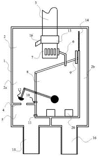
[0057] Different from Embodiment 1, in this embodiment, the second water outlet 16 communicating with the water collection chamber 2 is located at the upper or middle part of the casing. When the liquid level of the rainwater in the water collection cavity 2 reaches the overflow position, it is discharged through the second water outlet 16 and the rainwater is collected. In order to further optimize the structure, the float chamber 8 is directly formed by the baffle 21 and the side wall of the box body 1. In this embodiment, the water collection chamber is the left chamber, as Figure 4 As shown, and the second water outlet 16 for collecting rainwater is located on the upper part of the box body 1, and the filter plate 14 is arranged at the second water outlet 16, when the liquid channel of the first water outlet 15 is closed, the water collection The rainwater in the cavity 2 overflows the second water outlet 16 to be discharged.

[0058] Obviously, as a conventional alterna...


PUM


Abstract

The invention discloses a flow discarding and flow diversion device and its work method, particularly relates to a flow discarding and flow diversion device of a rainwater down pipe and a flow discarding and flow diversion method, and belongs to the technical field of urban water supply and drainage. The device includes a box body having a water collecting chamber, the water collecting chamber is internally provided with a float ball chamber, the box body is further provided with the rainwater down pipe from which rainwater enters, the lower end portion of the rainwater down pipe is provided with a water segregator, the water segregator introduces one part of liquid into the float ball chamber, the other part of liquid enters the water collecting chamber, the box body is provided with a first water outlet, the water collecting chamber and a liquid channel of the first water outlet are provided with float ball valves, float balls of the float ball valves are located in the float ball chamber, the box body is further provided with a second water outlet, when the liquid channel of the first water outlet is closed, liquid overflows to the second water outlet and is discharged, and the lower portion of the float ball chamber is provided with a liquid discharge hole used for water drainage. According to the device and the method, the early flow discarding and flow diversion problems of the earth surface, buildings and structures are solved, water resources are made full use of, and the practicability is higher.

Description

technical field [0001] The invention relates to an abandoned stream diversion device and a working method thereof, in particular to a rain downpipe abandoned stream diversion device and its abandoned stream diversion method, belonging to the technical field of urban rainwater collection and water supply and drainage. Background technique [0002] Rainwater abandonment is mainly used in rainwater collection and utilization systems. During the initial rainfall, the rainwater in the early stage is generally seriously polluted and the flow rate is relatively small. If the effect of abandonment is not good, impurities in the rainwater will enter the rainwater well, even if the hanging basket is used Filter the larger debris, but the small impurities in the initial rainwater will be collected into the rainwater well with the rainwater. After a long time, the small impurities will settle to the bottom of the pool, which will bring great trouble to the later cleaning work, and even ...

Claims


Application Information

Patent Timeline
Patent Type & Authority Applications(China)
IPC IPC(8): E03F1/00E03F5/10
CPCE03F1/00E03F5/101E03F2201/10
Inventor 谢刚
Owner SICHUAN MUYU ENVIRONMENTAL PROTECTION TECH CO LTD
Why Eureka
Try Eureka