Troweling machine

A troweling machine and engine technology, which is applied in the field of troweling machines, can solve problems such as increasing the labor intensity of operators, and achieve the effect of reducing labor intensity

Active Publication Date: 2017-09-22
上海捷舟工程机械有限公司
View PDF6 Cites 16 Cited by
  • Summary
  • Abstract
  • Description
  • Claims
  • Application Information

AI Technical Summary

Problems solved by technology

[0004] In the above technical solution, the operator sits on the seat and controls the forward or backward movement of the whole equipment by manipulating the operating lever. The operating lever controls and adjusts the inclination of the vertical axis through the transmission plate, connecting rod, rotating joint and swing rod. Angle, this kind of driving method requires the operator to repeatedly swing the operating lever during driving, which will increase the labor intensity of the operator

Method used


Image

  • Troweling machine
  • Troweling machine
  • Troweling machine

Examples


Embodiment Construction

[0036] The present invention will be further described in detail below in conjunction with the drawings.

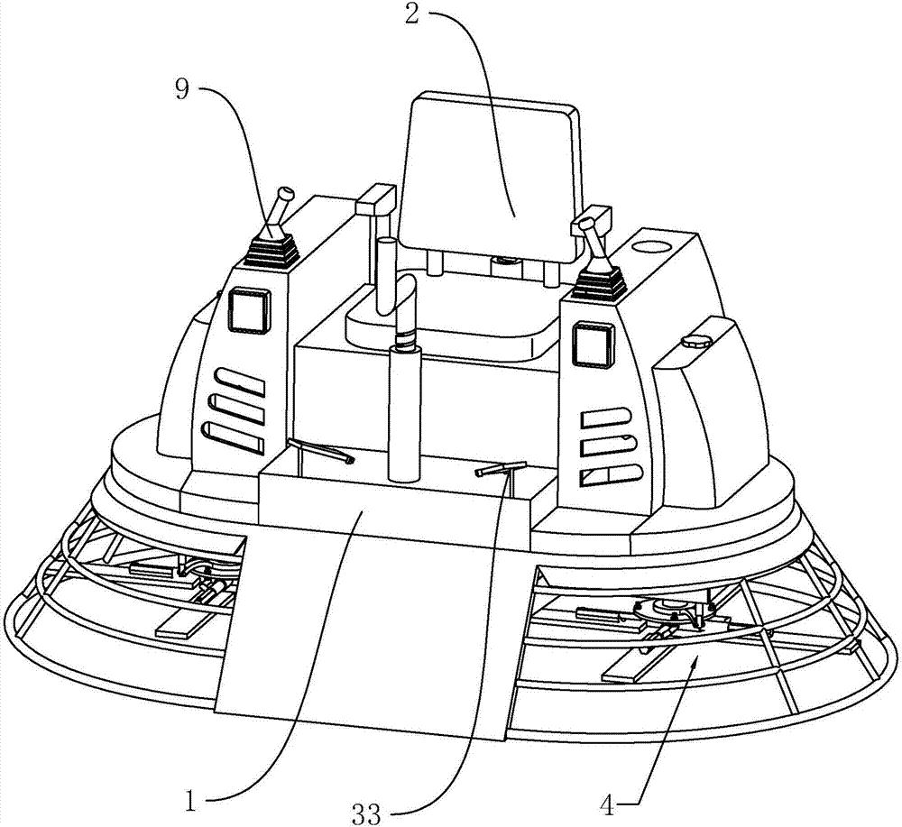
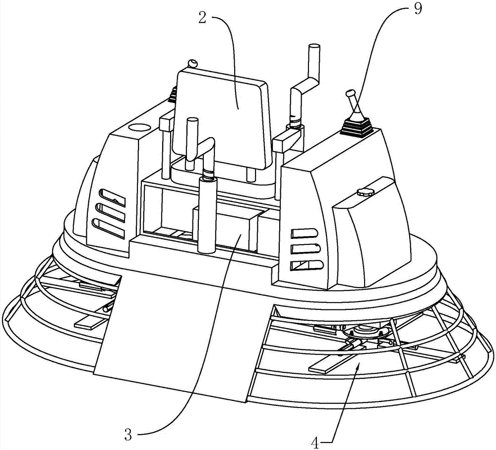
[0037] A trowel, combining Figure 1-2 As shown, it includes a rectangular parallelepiped chassis 1. A driver's seat 2 is fixedly installed in the upper middle of the chassis 1; a gasoline engine 3 is installed below the driver's seat 2; on both sides of the bottom of the chassis 1 and the driver's seat The center line of 2 is an axis-symmetrical wiper mechanism 4, and the engine 3 provides power for the wiper mechanism 4 to continuously rotate to achieve a smoothing effect on the ground.

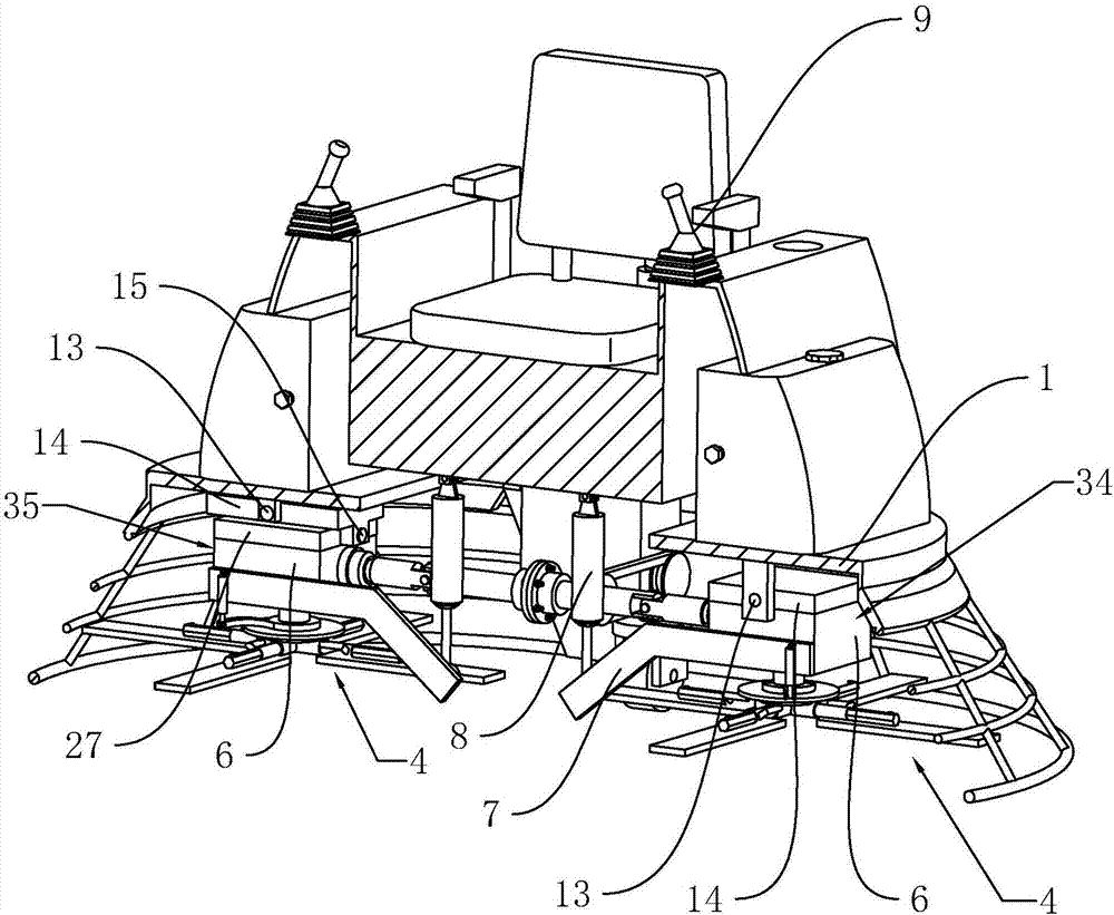
[0038] Reference image 3 As shown, on both sides of the chassis 1 corresponding to the two wiper mechanisms 4, a one-way mounting assembly 34 and a two-way mounting assembly 35 are respectively provided; the one-way mounting assembly 34 includes a rotatably connected to the chassis 1. And the axial connection with the two wiping mechanisms 4 is perpendicular to the straight shaft 13, a mou...


PUM


Abstract

The invention discloses a troweling machine which comprises a chassis, a driving seat arranged on the chassis, an engine mounted on the chassis, troweling piece mechanisms mounted on the two sides of the chassis and symmetrically arranged with the central line of the driving seat as the axis and a transmission mechanism connected between the engine and the troweling piece mechanisms. The troweling piece mechanisms are both connected with mounting bases which are rotatably connected to the chassis; rotation shafts of the mounting bases are perpendicular to a connection line between the two mounting bases; the mounting bases are both connected with swinging rods; straight-travelling oil cylinders in one to one correspondence with the swinging rods are hinged to the chassis; piston rods of the straight-travelling oil cylinders are hinged to the ends, away from the mounting bases, of the swinging rods; the driving seat is provided with operation handles in one to one correspondence with the straight-travelling oil cylinders; the chassis is provided with a hydraulic oil tank communicating with the straight-travelling oil cylinders; and the operation handles control the straight-travelling oil cylinders to conduct oil inlet or oil outlet. The troweling machine can relieve the labor intensity.

Description

Technical field [0001] The invention relates to concrete pavement processing equipment, in particular to a trowel. Background technique [0002] The trowel is also called the receiver. Its main structure is a spatula rotor driven by a gasoline engine, and a spatula is installed on the bottom of the cross in the middle of the rotor. It is a rough and fine troweling machine for concrete surface. The surface constructed by the machine is smoother and flatter than the surface constructed manually, which can greatly improve the compactness and wear resistance of the concrete surface. The floor trowel can be widely used for lifting, troweling and troweling the concrete surface of high-standard factories, warehouses, parking lots, squares, airports and frame buildings. [0003] The patent document of Chinese Patent Publication No. CN204081421U discloses a driving trowel, which includes a base on which a seat is arranged. At least two vertical shaft assemblies are connected to the base in...

Claims


Application Information

Patent Timeline
Patent Type & Authority Applications(China)
IPC IPC(8): E04F21/24
CPCE04F21/244E04F21/247
Inventor 吴云舟
Owner 上海捷舟工程机械有限公司
Why Eureka
Try Eureka