Laser tracker with two measuring function alities

A technology of laser tracker and function, applied in the field of laser tracker, can solve the problems of high cost and complicated production process

Active Publication Date: 2017-09-22
LEICA GEOSYSTEMS AG
View PDF9 Cites 10 Cited by
  • Summary
  • Abstract
  • Description
  • Claims
  • Application Information

AI Technical Summary

Problems solved by technology

Although each ADM sends their measurement radiation via a single exit optical unit, they are in each case separate, independent units
The need to provide two completely independent, separate absolute position measuring devices is disadvantageously complex in terms of production process and therefore expensive

Method used


Image

  • Laser tracker with two measuring function alities
  • Laser tracker with two measuring function alities
  • Laser tracker with two measuring function alities

Examples


Embodiment Construction

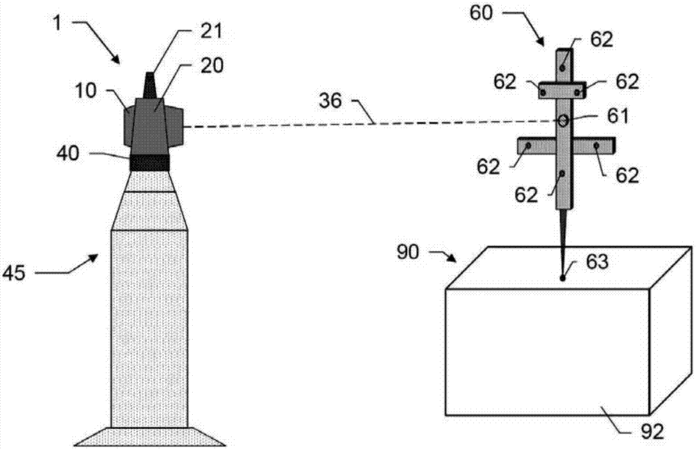
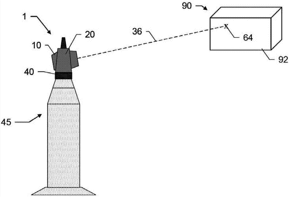
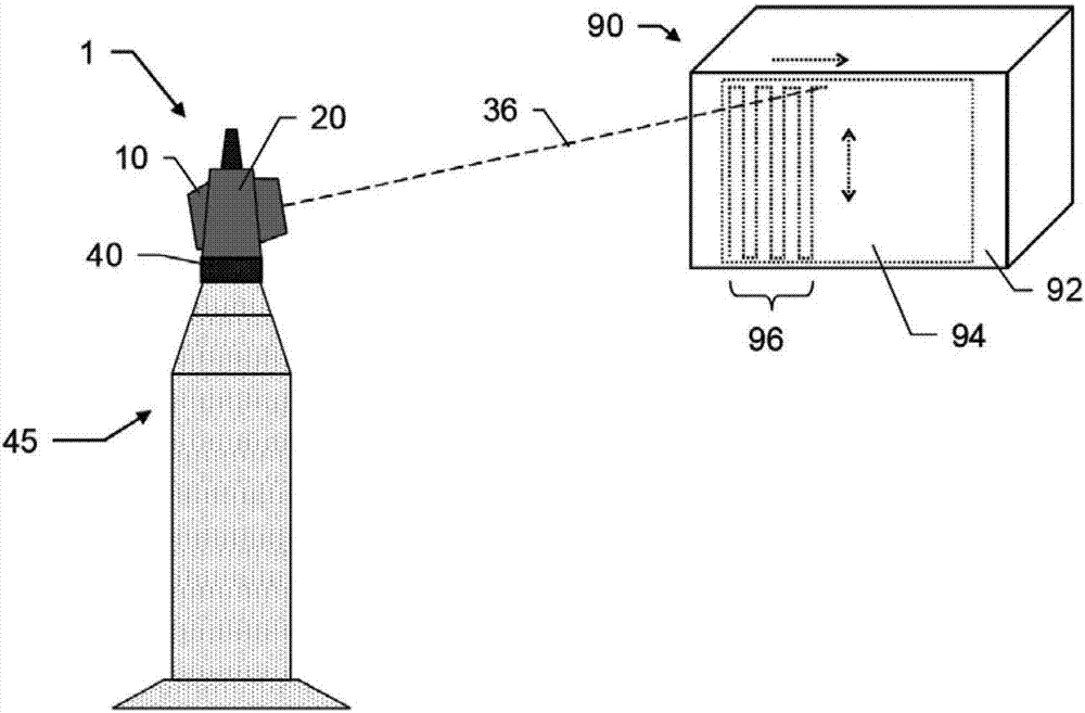
[0046] figure 1 , figure 2 and image 3 An exemplary embodiment of a laser tracker 1 according to the invention is shown. The shown laser tracker 1 comprises a base 40 , a support body 20 mounted on the base 40 and having a handle 21 , and a beam guiding unit 10 mounted on two struts of the support body 20 . The laser tracker 1 is arranged on a support 45 and comprises: a control and evaluation unit; an angle sensor for detecting the angle of rotation of the beam guiding unit 10 relative to the base 40; and an optical distance measuring unit with at least one first beam source (e.g. one or more laser diodes or superluminescent LEDs), at least one first detection unit (e.g. electronic distance measurement unit), absolute distance unit (ADM) or interferometer unit (IFM) (not shown here) . With suitable synchronization of the angle sensors, the two angles and at least one distance determined by the first measurement radiation 36 can be combined to form the 3D polar coordinat...


PUM


Abstract

A laser tracker with two measuring function alities. A laser tracker (1) for determining the industrial coordinate position of the target (61, 64), wherein the laser tracker (1) comprises at least: a control and evaluation unit, a base (40) and a beam guide unit (10), means for detecting the rotation angle of the beam guide unit with respect to the base, and means having at least a first beam source (30) and a first optical distance measuring unit (2) of a first detection unit(12).The distance measurement unit (2) and the control and evaluation unit are designed to implement the first measurement function and the second measurement function; for this purpose, at least one element of the distance measuring unit (2) is designed for dual use in both the first measurement function and the second measurement function. The first measurement function is designed for the coordinate position determination of the retroreflective target (61), and the second measurement function is designed for the coordinate position determination for the diffuse scattering target (64).

Description

technical field [0001] The invention relates to a laser tracker for industrial coordinate position determination of objects with an optical distance measuring unit according to claim 1 and a method for coordinate position determination according to claim 13 . Background technique [0002] Laser trackers are used in industrial surveying, such as, for example, for coordinate position determination of points in inspection environments such as parts of vehicles or continuous position monitoring of moving machine parts. Such laser trackers are designed for the coordinate position determination of said target points and generally for the continuous tracking of retroreflective target points. In this case, the target point may be represented by a retroreflective unit (eg cube prism) that is the target of an optical measurement beam (in particular a laser beam) generated by the beam source of the measurement device or of the measurement device. The laser beam is reflected back to th...

Claims


Application Information

Patent Timeline
Patent Type & Authority Applications(China)
IPC IPC(8): G01C15/00G01S17/66G01B11/00G01S7/48G01S17/10G01S17/32G01S17/87
CPCG01B11/002G01C15/002G01S7/4808G01S17/66G01S17/10G01S17/32G01S17/87G01S7/4812G01S7/4815G01S17/42G01S7/4817
Inventor T·鲁斯V·马克西莫维奇
Owner LEICA GEOSYSTEMS AG
Why Eureka
Try Eureka