
Multi-objective optimization three-phase unbalanced switch control method

A multi-objective optimization, balanced switching technology, applied in the direction of reducing the asymmetry of the polyphase network, eliminating/reducing the asymmetry of the polyphase network, etc., can solve the three-phase voltage and current imbalance of the power supply system, affecting the normal power consumption of users, Reduce the quality of power supply and other problems to achieve the effect of improving the quality and reliability of power supply, reducing the rate of user complaints, and improving the quality of power supply

Active Publication Date: 2017-09-22
CHINA EPRI SCIENCE & TECHNOLOGY CO LTD +3
View PDF3 Cites 16 Cited by
  • Summary
  • Abstract
  • Description
  • Claims
  • Application Information

AI Technical Summary

Problems solved by technology

[0002] In the low-voltage distribution network system, there are a large number of single-phase and asymmetrical loads, and the operation of three-phase loads changes randomly. These loads will cause three-phase unbalance in the power distribution system, resulting in unbalanced three-phase voltage and current in the power supply system. Negative-sequence voltage and negative-sequence current will be generated, which will reduce the quality of power supply and affect the normal power consumption of users in severe cases. At the same time, it will increase the loss of lines and transformers, reduce the reliability of power supply, and even cause serious power failures such as large-scale power outages and neutral line blowouts. as a result of

Method used


Image

  • Multi-objective optimization three-phase unbalanced switch control method
  • Multi-objective optimization three-phase unbalanced switch control method
  • Multi-objective optimization three-phase unbalanced switch control method

Examples


Embodiment Construction

[0036] The specific implementation manners of the present invention will be further described in detail below in conjunction with the accompanying drawings.

[0037] The following description and drawings illustrate specific embodiments of the invention sufficiently to enable those skilled in the art to practice them. Other embodiments may incorporate structural, logical, electrical, process, and other changes. The examples merely represent possible variations. Individual components and functions are optional unless explicitly required, and the order of operations may vary. Portions and features of some embodiments may be included in or substituted for those of other embodiments. The scope of embodiments of the present invention includes the full scope of the claims, and all available equivalents of the claims. These embodiments of the present invention may be referred to herein, individually or collectively, by the term "invention", which is for convenience only and is not...


PUM


Abstract

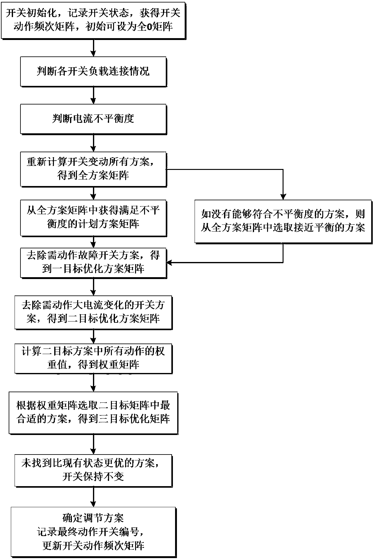
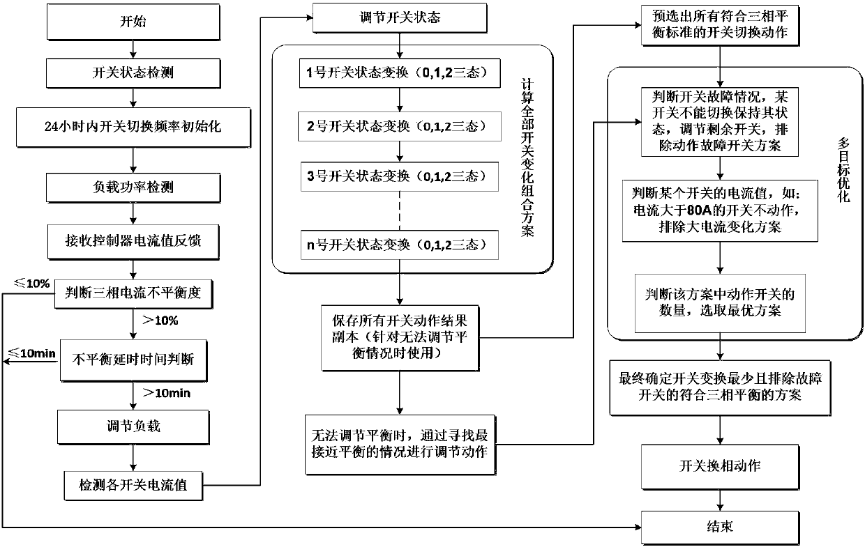
The invention relates to a multi-objective optimization three-phase unbalanced switch control method comprising the steps that the corresponding three-phase current unbalance degree is calculated according to sampling current; after a three-phase unbalanced switch is accessed to a power grid to work, a controller cyclically detects the three-phase current value and the unbalance degree of each phase of current, and no operation is performed if the three-phase current is balanced until the next detection instruction; and if the unbalance degree of a certain phase of current exceeds the preset value, the transformer load condition is judged and then the three-phase unbalanced switch is judged; when the adjusting process of the three-phase unbalanced switch is switched on, the controller performs permutation and combination on all the states of all the switches, all the switch changeover schemes are traversed and the corresponding three-phase current unbalance degree of all the switch changeover schemes is stored so as to perform multi-objective optimization. The load condition can be periodically and actively monitored so that real-time monitoring can be realized, multiple practical problems about the switch fault condition and the switch service life can be solved, and the problems of high current phase commutation and frequent phase commutation of a certain switch can be avoided.

Description

technical field [0001] The invention relates to a three-phase unbalance control method, in particular to a multi-objective optimized three-phase unbalance switch control method. Background technique [0002] In the low-voltage distribution network system, there are a large number of single-phase and asymmetrical loads, and the operation of three-phase loads changes randomly. These loads will cause three-phase unbalance in the power distribution system, resulting in unbalanced three-phase voltage and current in the power supply system. Negative-sequence voltage and negative-sequence current will be generated, which will reduce the quality of power supply and affect the normal power consumption of users in severe cases. At the same time, it will increase the loss of lines and transformers, reduce the reliability of power supply, and even cause serious power failures such as large-scale power outages and neutral line blowouts. as a result of. [0003] Three-phase unbalance con...

Claims


Application Information

Patent Timeline
IPC IPC(8): H02J3/26
CPCH02J3/26Y02E40/50
Inventor 尹元亚刘洋洋叶卫华缪伟夏民崔椿洪葛明明袁蒙贲宝强周娴姊任思源
Owner CHINA EPRI SCIENCE & TECHNOLOGY CO LTD
Learn More