Power assembly and assembling method thereof

A technology for power components and power devices, applied in electrical components, electrical equipment structural parts, cooling/ventilation/heating transformation, etc. The effect of installation reliability, avoidance of failure and damage, and simple overall structure

Active Publication Date: 2017-09-22
ZHUZHOU CSR TIMES ELECTRIC CO LTD
View PDF5 Cites 2 Cited by
  • Summary
  • Abstract
  • Description
  • Claims
  • Application Information

AI Technical Summary

Problems solved by technology

However, there are the following problems: A. The support problem of the PCB board cannot be well solved, and the use of a conventional support structure is not conducive to rapid assembly; B. It is a horizontal layout structure, which cannot make good use of the vertical space (or the depth of the cabinet) space); C. Power device pins need to be bent, and the dimensional accuracy of the bending is relatively high, which increases the assembly man-hour and easily causes device damage
However, there are the following problems: the power devices need to be fixed on the radiator separately, and cannot be assembled into a module for maintenance and installation
Generally, the heat dissipation of power devices adopts the method of direct contact with the heat sink, but as the power density becomes higher and higher, the volume of the heat sink becomes larger and larger. At this time, only tooling can be used for assembly. This assembly method It affects the assembly efficiency and is not conducive to after-sales maintenance. At the same time, the secondary assembly is prone to mechanical stress, resulting in deformation, and it is prone to failure and damage after long-term operation

Method used


Image

  • Power assembly and assembling method thereof
  • Power assembly and assembling method thereof
  • Power assembly and assembling method thereof

Examples


Embodiment Construction

[0035] The present invention will be described in further detail below in conjunction with the accompanying drawings and specific embodiments.

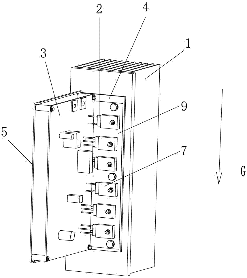
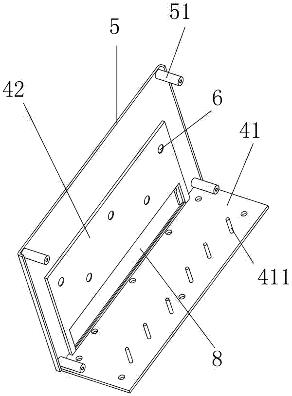
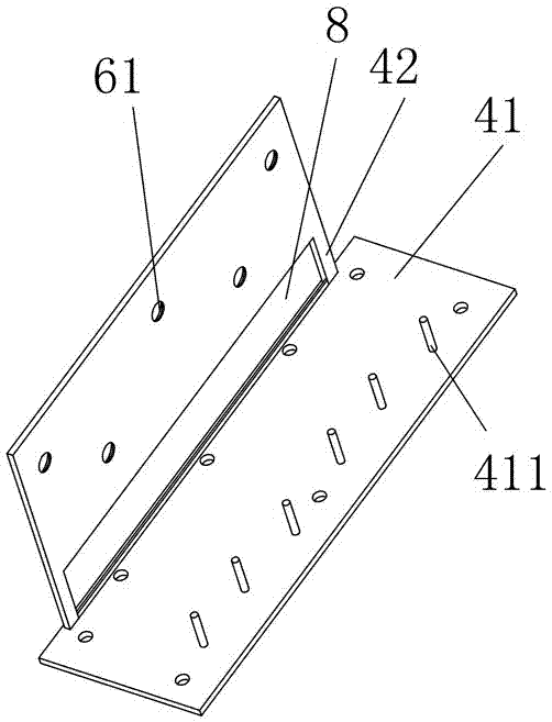
[0036] Such as figure 1 As shown, the power assembly of this embodiment includes a heat sink 1, a power device 2, a PCB board 3, a heat dissipation bottom plate 4, and a supporting side plate 5. The heat dissipation bottom plate 4 is installed on the surface of the heat sink 1, and the supporting side plate 5 and the heat dissipation bottom plate 4 connected, the power device 2 is installed on the heat dissipation base plate 4 through fasteners, the PCB board 3 is installed on the support side plate 5 through fasteners and arranged vertically with the heat dissipation base plate 4, the pins of the power device 2 are arranged facing the PCB board 3 and Solder with PCB board 3. Wherein, the heat dissipation bottom plate 4 is installed on the surface of the radiator 1 through a plurality of mounting bolts to ensure uniform stress;

[0...


PUM


Abstract

The invention discloses a power assembly comprising a radiator, a power device, a PCB, a heat dissipation base plate and a support side plate, wherein the heat dissipation base plate is installed on the surface of the radiator, the support side plate is connected with the heat dissipation base plate, the power device is installed on the heat dissipation base plate via a fastener, the PCB is installed on the support side pate via the fastener and arranged to be vertical to the heat dissipation base plate, pins of the power device are arranged to facing the PCB and welded with the PCB. The power assembly has the advantages of being simple in process, high in efficiency and capable of avoiding generation of mechanical stress when in assembling. The assembling method comprises the steps of connecting the support side plate with the heat dissipation base plate; installing the PCB on the support side plate and pre-fastening, and installing the power device on the heat dissipation base plate and pre-fastening; welding the power device with the PCB; screwing a pre-fastened bolt in place, and removing dust and excess materials, thus completing installation of the power device. The method has the advantages of being simple in process, high in efficiency, and capable of eliminating the mechanical stress caused by reassembly after welding.

Description

technical field [0001] The invention relates to a semiconductor device, in particular to a power assembly and an assembly method thereof. Background technique [0002] Patent document CN 104658921 A discloses a heat sink assembly process for power semiconductor devices. In this process, the power semiconductor device is first fixed on the heat-conducting substrate, and then the single board and the heat-conducting substrate on which the power semiconductor device is fixed are integrally crimped on the heat sink. superior. On the one hand, this technical solution solves the problem that the power single board cannot be produced in a modular manner, realizes the simple installation and maintenance of the power single board, and can improve the efficiency of the production and processing process; on the other hand, it can facilitate the storage and transportation of maintenance spare parts, and the operation site Rapid maintenance and replacement. Therefore, this technical so...

Claims


Application Information

Patent Timeline
Patent Type & Authority Applications(China)
IPC IPC(8): H05K7/02H05K7/20
CPCH05K7/023H05K7/205
Inventor 刘玉柱蹇芳唐海燕陈艺峰唐洲朱淇凉张洪浩廖远辉吴建雄管仁德姜扬帆姚明
Owner ZHUZHOU CSR TIMES ELECTRIC CO LTD
Why Eureka
Try Eureka