Intelligent lubricating oil way cleaning system and working method thereof

A lubricating oil circuit and cleaning system technology, applied in cleaning methods and appliances, chemical instruments and methods, cleaning hollow objects, etc., can solve problems such as affecting the lubrication effect of lubricating oil, increasing the rotation resistance of gears, and engine failure, etc., to achieve Automatic cleaning, convenient and hygienic effect

Pending Publication Date: 2017-09-26
CHANGZHOU ZHONGJIE NEW MATERIAL TECH CO LTD
View PDF6 Cites 1 Cited by
  • Summary
  • Abstract
  • Description
  • Claims
  • Application Information

AI Technical Summary

Problems solved by technology

When it accumulates more and more, it will affect the pumping of lubricating oil, increase the resistance of gear rotation, affect the lubricating effect of lubricating oil, and cause engine failure

Method used


Image

  • Intelligent lubricating oil way cleaning system and working method thereof

Examples


Embodiment 1

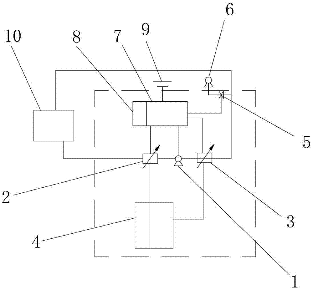
[0019] Such as figure 1 As shown, the intelligent lubricating oil circuit cleaning system of the present embodiment includes a circulation tank 4 for holding a lubricating oil cleaning agent, an oil pump 1, a first three-way solenoid valve 2, a second three-way solenoid valve 3, a first three-way solenoid valve, and a three-way solenoid valve. The first interface of the solenoid valve 2 is sealed and connected with the oil outlet of the fuel tank 10 through the oil pipe, and the second interface of the first three-way solenoid valve 2 is connected with the bottom of the circulation tank 4 through the oil pipe. The first three-way solenoid valve The third interface of 2 is sealedly connected with the oil inlet port of oil pump 1 through the oil pipe; the oil outlet port of the oil pump 1 is sealed connected with the first interface of the second three-way solenoid valve 3 through the oil pipe, and the The second interface is sealed connected with the circulation tank 4 through ...

Embodiment 2

[0021] The working method of the above-mentioned intelligent lubricating oil circuit cleaning system includes the following steps:

[0022] A. Drain the lubricating oil in the oil tank 10 through the oil outlet, and fill the lubricating oil cleaning agent into the circulation tank 4; connect the first interface of the first three-way solenoid valve 2 to the oil outlet of the oil tank 10 through the oil pipe. , the second interface of the second three-way solenoid valve 3 is sealed and connected with the oil inlet of the fuel tank 10 through the oil pipe, and the second interface of the second three-way electromagnetic valve 3 is sealed and connected with the circulation tank 4 through the oil pipe to form a circulation path.

[0023] B. The control circuit 7 controls the first interface of the first three-way solenoid valve 2 to close, the second interface and the third interface to open, controls the first interface and the third interface of the second three-way electromagnet...


PUM


Abstract

The invention relates to an intelligent lubricating oil way cleaning system and a working method thereof. The intelligent lubricating oil way cleaning system comprises a circulating tank, an oil pump, a first three-way solenoid valve and a second three-way solenoid valve; a first port of the first three-way solenoid valve is in sealed connection with an oil outlet of an oil tank through an oil pipe; a second port of the first three-way solenoid valve is in sealed connection with the circulating tank through an oil pipe; a third port of the first three-way solenoid valve is in sealed connection with an oil inlet of the oil pump through an oil pipe; an oil outlet of the oil pump is in sealed connection with a first port of the second three-way solenoid valve through an oil pipe; a second port of the second three-way solenoid valve is in sealed connection with an oil inlet of the oil tank through an oil pipe; and a third port of the second three-way solenoid valve is in sealed connection with the circulating tank through an oil pipe. The intelligent lubricating oil way cleaning system further comprises a control circuit; output ends of the control circuit are electrically connected with the first three-way solenoid valve, the oil pump and the second three-way solenoid valve; and the control circuit is used for controlling the first three-way solenoid valve, the oil pump and the second three-way solenoid valve to be opened and closed.

Description

technical field [0001] The invention relates to the technical field of cleaning equipment, in particular to an intelligent lubricating oil circuit cleaning system and a working method thereof. Background technique [0002] When the engine is running, the lubricating oil circulates under high temperature and high pressure. There are inevitably dust and metal debris in the lubricating system. In addition, gasoline, water and other impurities enter the cylinder, and sludge and dirt will form in the crankcase. , so that the lubricating oil will gradually lose its lubricating ability. Some impurities can be released when changing the lubricating oil, but the problem still exists because a considerable part of the sludge and varnish in the waste lubricating oil remains in the system. After the new lubricating oil is added, it will quickly dissolve with the sludge and varnish, and the cycle will repeat. The lubrication system will be in trouble due to the existence of sludge and v...

Claims


Application Information

Patent Timeline
Patent Type & Authority Applications(China)
IPC IPC(8): B08B9/08B08B9/093
CPCB08B9/08B08B9/093
Inventor 苏扬王军
Owner CHANGZHOU ZHONGJIE NEW MATERIAL TECH CO LTD
Why Eureka
Try Eureka