Agricultural machinery surface cleaning equipment

A technology for surface cleaning and agricultural machinery, applied in cleaning methods and utensils, cleaning methods using liquids, cleaning methods using tools, etc., can solve the problems of difficult cleaning, laborious cleaning, low efficiency, etc. Efficient cleaning effect

Inactive Publication Date: 2022-05-06
郭文英
View PDF0 Cites 0 Cited by
  • Summary
  • Abstract
  • Description
  • Claims
  • Application Information

AI Technical Summary

Problems solved by technology

[0004] The purpose of the present invention is to solve the problem of cleaning the surface of agricultural machinery in the prior art, which is usually manual washing, which wastes manpower and is inefficient, and some larger agricultural machinery is very laborious to clean, and it is often difficult to clean manually The shortcomings of the proposed agricultural machinery surface cleaning equipment

Method used


Image

  • Agricultural machinery surface cleaning equipment
  • Agricultural machinery surface cleaning equipment
  • Agricultural machinery surface cleaning equipment

Examples


Embodiment 1

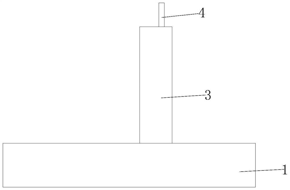
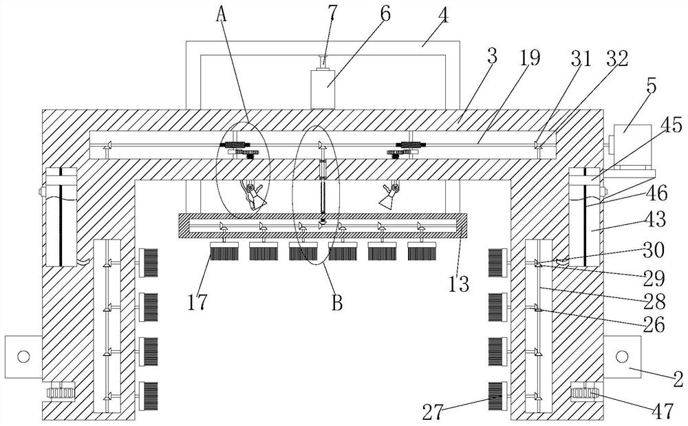
[0030] refer to Figure 1-6, a kind of agricultural machine surface cleaning equipment, comprises U-shaped frame base 1, and the inner wall of both sides of U-shaped frame base 1 is provided with chute, and slide block 2 is all slidably installed in two chute, two slide blocks 2 The sides close to each other are fixedly connected with the same gantry frame 3 by welding, and two sliding holes are opened on the gantry frame 3, and the same gantry frame 4 is slidably installed in the two sliding holes, and the bottom end of the gantry frame 4 is connected There is a first cleaning mechanism, and a second cleaning mechanism is arranged on the inner walls of both sides of the gantry frame body 3, and two water spraying mechanisms are arranged on the top inner wall of the gantry frame body 3, and cleaning liquid is arranged on the two water spraying mechanisms mechanism, the right side of the gantry frame body 3 is fixedly connected with a first motor plate by welding, and the top o...

Embodiment 2

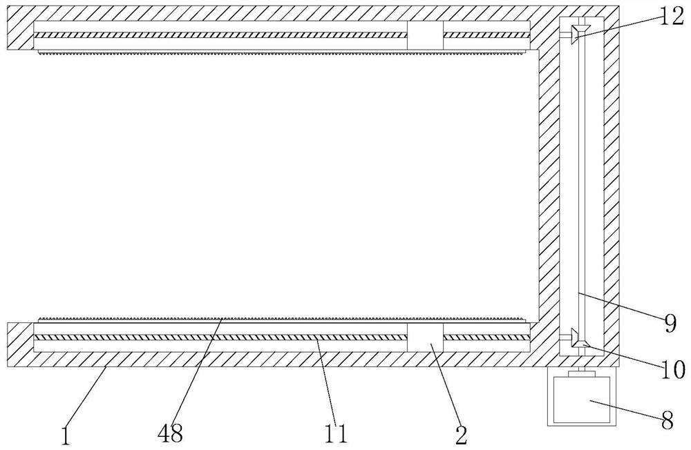
[0042] The difference from Embodiment 1 is that the cleaning liquid mechanism includes a liquid storage chamber 43 arranged in the gantry frame 3 and a liquid outlet head 44 arranged on the spray head 33, the liquid outlet head 44 is connected with a connecting pipe, and the connecting pipe One end of one end is connected with the liquid storage chamber 43, and the rectangular piston plate 45 is slidingly installed in the liquid storage chamber 43, and the second threaded rod 46 is rotatably installed in the liquid storage chamber 43, and the second threaded hole is opened on the rectangular piston plate 45. Two threaded rods 46 are threadedly installed in the second threaded holes, grooves are provided on both sides of the gantry frame body 3, and the bottom end of the second threaded rods 46 extends into the grooves and is fixedly connected with a second rotating gear 47 , the inner wall of the U-shaped frame base is fixedly connected with a rack 48, the rack 48 is meshed wit...


PUM


Abstract

The invention belongs to the technical field of agricultural machinery, and particularly relates to agricultural machinery surface cleaning equipment which comprises a U-shaped frame base, sliding grooves are formed in the inner walls of the two sides of the U-shaped frame base, sliding blocks are installed in the two sliding grooves in a sliding mode, the sides, close to each other, of the two sliding blocks are fixedly connected with the same gantry frame body, and two sliding holes are formed in the gantry frame body; a same portal frame is slidably mounted in the two sliding holes, a first cleaning mechanism is connected to the bottom end of the portal frame, second cleaning mechanisms are arranged on the inner walls of the two sides of the gantry frame body, two water spraying mechanisms are arranged on the inner wall of the top of the gantry frame body, and cleaning liquid mechanisms are arranged on the two water spraying mechanisms; the right side of the gantry frame body is fixedly connected with a first motor plate. According to the agricultural machinery surface cleaning device, surface parts of agricultural machinery can be fully automatically cleaned, the surface of the agricultural machinery can be comprehensively and thoroughly cleaned, comprehensive clean water spraying and automatic spraying of a proper amount of cleaning liquid can be achieved while cleaning is conducted, and the cleaning effect is improved.

Description

technical field [0001] The invention belongs to the technical field of agricultural machinery, in particular to an agricultural machinery surface cleaning device. Background technique [0002] Agricultural machinery refers to various machinery used in crop planting and animal husbandry production, as well as in the primary processing and handling of agricultural and animal products. Agricultural machinery includes agricultural power machinery, farmland construction machinery, soil tillage machinery, planting and fertilization machinery, plant protection machinery, farmland drainage and irrigation machinery, crop harvesting machinery, agricultural product processing machinery, animal husbandry machinery and agricultural transportation machinery, etc. [0003] The current method of cleaning the surface of agricultural machinery is usually manual washing, which is a waste of labor and low in efficiency, and some larger agricultural machinery is very laborious to clean, and it i...

Claims


Application Information

Patent Timeline
Patent Type & Authority Applications(China)
IPC IPC(8): B08B1/04
CPCB08B1/002B08B1/04B08B3/024B08B13/00
Inventor 郭文英
Owner 郭文英
Why Eureka
Try Eureka