Self-circulation treatment casing for simultaneously improving stator corner region flowing

A technology for handling casing and self-circulation, applied in the direction of machines/engines, liquid fuel engines, components of pumping devices for elastic fluids, etc. The limited range of working conditions and other problems can improve the flow of the rotor tip, avoid the rotating stall of the rotor, and solve the problem of circumferential unevenness.

Active Publication Date: 2017-09-26
BEIHANG UNIV
View PDF9 Cites 10 Cited by
  • Summary
  • Abstract
  • Description
  • Claims
  • Application Information

AI Technical Summary

Problems solved by technology

[0002] The compressor is the core component of the aviation gas turbine engine. It is composed of multi-stage rotors and stators arranged in a staggered order. Its function is to increase the gas pressure rise; in the flow inside the compressor, due to the small flow space, the reverse pressure of the fluid The gradient effect is strong, and it has a complex vortex structure; the corner separation structure located at the stator end zone and the leakage flow structure located at the rotor tip are the main secondary flow structures inside the compressor, and are the main causes of flow loss and blockage inside the compressor. The source has a vital impact on the performance of the compressor's pressure ratio, efficiency, and margin. In severe cases, it will cause the stall and surge of the compressor, which will bring disastrous consequences; after decades of research, many scientific research works Researchers have had a deep understanding of the compressor stator corner flow and rotor blade tip flow, but due to the limitations of space and the complexity of the flow, it has not been well realized based on the existing research results. Effective control of the flow in the compressor; in particular, making full use of the characteristics of the step-by-step pressurization of the flow in the compressor, through a certain self-circulation adjustment mechanism, while using and improving the flow structure that is not conducive to performance, to achieve the purpose of improving the performance of the compressor
[0003] For the compressor stator, the flow congestion caused by three-dimensional corner separation/stall makes the performance of the compressor drop sharply; the development of modern aero-engines puts forward higher requirements on the performance of the compressor, especially the increase of single-stage load and more Wide effective working range is required; however, with the increase of compressor load, t

Method used


Image

  • Self-circulation treatment casing for simultaneously improving stator corner region flowing
  • Self-circulation treatment casing for simultaneously improving stator corner region flowing
  • Self-circulation treatment casing for simultaneously improving stator corner region flowing

Examples


Embodiment 1

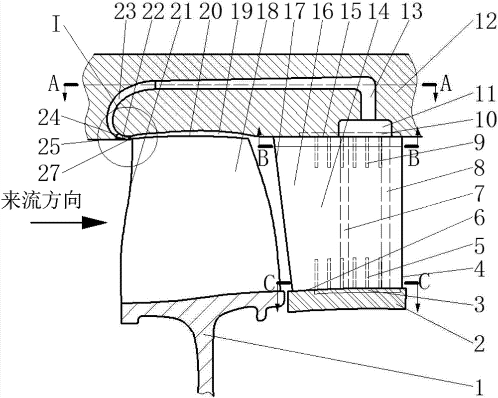
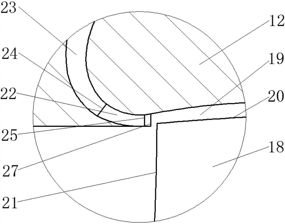
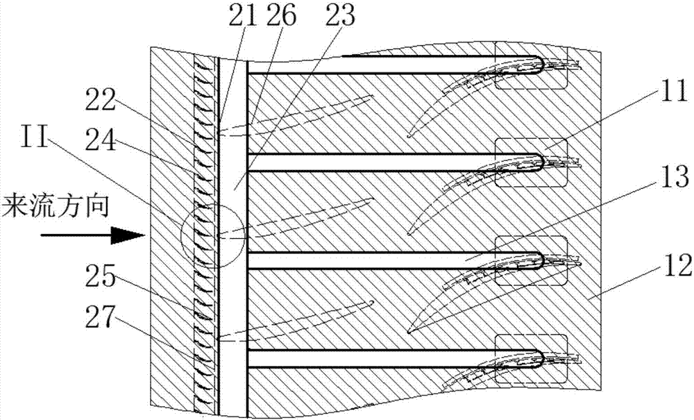
[0028] Such as figure 1 , figure 2 As shown, the self-circulation treatment casing of the present invention includes target rotor blades 18, downstream stator blades 16, casing 12 and the air induction pipe 13 structure located inside casing 12; There is a blade tip gap 19 between the blade tip 20 and the casing 12, the downstream stator blade 16 is located downstream of the target rotor blade 18, one side of the stator 16 is seamlessly connected with the casing 12, and has a casing side end wall 15, and the other The hub 2 is connected to one side and has a hub-side end wall 6 .

[0029] Such as Figure 5 As shown, the suction surface 28 casing side end area of ​​the downstream stator blade 16, the hub side end area and the casing end wall 15, and the hub end wall 6 are arranged with a combined suction groove 3, 5, 9, 10 structure; There are a plurality of suction grooves 9 on the suction surface 28 of the casing side of the stator blade 16, all of which are located in th...

Embodiment 2

[0033] This embodiment is basically the same as Embodiment 1, except that there are multiple rotor-stator rows between the target rotor and the downstream stator.


PUM


Abstract

The invention relates to multistage axial flow air compressor treatment casings, and discloses a self-circulation treatment casing for simultaneously improving stator corner region flowing. The self-circulation treatment casing comprises a target rotor blade, a downstream stator blade, a casing body and an air guide pipe structure located in the casing body. A flow guide cavity structure penetrating the whole circumferential direction is arranged at the position, on the front edge of a target rotor blade tip, in the casing body. Flow guide cavity outlet front guide vanes used for adjusting the jet flow direction are circumferentially and evenly arranged on the front edge of a flow guide cavity outlet, and the outlet directions of the guide vanes are consistent with the pre-rotating direction of the target rotor blade tip. According to the characteristic of stage-by-stage pressurization of a multistage air compressor, self-adaptive suction and jet flow are formed under the action of differential pressure of a downstream stator blade combined suction groove and the flow guide cavity outlet of the target rotor blade tip; separated flowing of a stator three-dimensional corner region of the air compressor is effectively restrained, and meanwhile moving blade rotating stall is prevented from happening too early through circumferentially-even jet flow with the pre-rotating direction consistent with that of the rotor blade tip; the rotor blade rotating stability and margin are increased; and the stable work condition range of the air compressor is widened.

Description

technical field [0001] The invention relates to a self-circulation processing casing of a multistage axial flow compressor, in particular to a self-circulation processing casing which simultaneously improves the flow in the corner area of ​​a stator. Background technique [0002] The compressor is the core component of the aviation gas turbine engine. It is composed of multi-stage rotors and stators arranged in a staggered order. Its function is to increase the gas pressure rise; in the flow inside the compressor, due to the small flow space, the reverse pressure of the fluid The gradient effect is strong, and it has a complex vortex structure; the corner separation structure located at the stator end zone and the leakage flow structure located at the rotor tip are the main secondary flow structures inside the compressor, and are the main causes of flow loss and blockage inside the compressor. The source has a vital impact on the performance of the compressor's pressure rati...

Claims


Application Information

Patent Timeline
IPC IPC(8): F04D29/52F04D29/54F04D29/38F04D27/00F04D19/02
CPCF04D19/02F04D27/002F04D29/324F04D29/522F04D29/542F04D29/544F05D2240/124F05D2240/303F05D2240/307F04D29/682F04D29/684
Inventor 柳阳威唐雨萌陆利蓬王鸣
Owner BEIHANG UNIV
Why Eureka
Try Eureka