Drive half axle structure convenient to demount and demounting method thereof

A technology of drive half shaft and body, applied in the field of drive half shaft structure and its disassembly, which can solve the problems of inconvenient disassembly and maintenance of the drive half shaft, and achieve the effects of improving disassembly processability, ensuring safety, and reducing labor intensity

Inactive Publication Date: 2017-09-26
泸州开士乐工程技术有限责任公司
View PDF6 Cites 1 Cited by
  • Summary
  • Abstract
  • Description
  • Claims
  • Application Information

AI Technical Summary

Problems solved by technology

[0004] The purpose of the present invention is to overcome the deficiencies of the prior art, and the purpose is to provide an easy-to-disassemble drive half-shaft structure and its disassembly method, and solve the problem of inconvenient disassembly and maintenance of the drive half-shaft

Method used


Image

  • Drive half axle structure convenient to demount and demounting method thereof
  • Drive half axle structure convenient to demount and demounting method thereof
  • Drive half axle structure convenient to demount and demounting method thereof

Examples


Embodiment 1

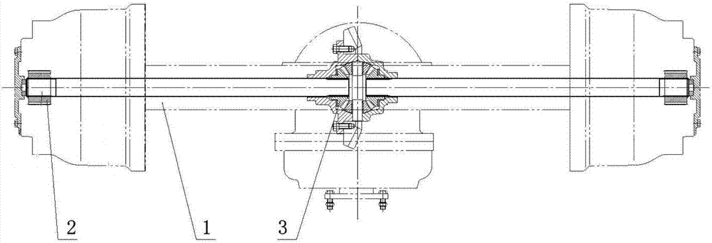
[0034] Such as image 3 As shown, the present invention is an easy-to-disassemble drive half-shaft structure, including a drive half-shaft body 1, one end of the drive half-shaft body 1 is connected to the wheel reducer 2, and the other end of the drive half-shaft body 1 is connected to the main body of the vehicle. The reducer 3 is connected, characterized in that:

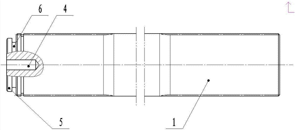
[0035] A boss 5 is provided at the end of the connecting end of the driving half shaft body 1 and the wheel reducer 2 , and an annular groove 6 is arranged on the boss 5 .

[0036] The boss 6 is an annular boss.

[0037] A threaded hole 4 is added in the center of the end face of the boss 5 .

[0038] The threaded hole 4 is an M10 threaded hole.

[0039] On the basis of ensuring the original design and installation dimensions of the driving half shaft, we added an M10 threaded hole in the center of the end face of the driving half shaft connected to the wheel side reducer (such as image 3 ; Or open a groove ...

Embodiment 2

[0042] Such as image 3 As shown, the present invention is an easy-to-disassemble drive half-shaft structure disassembly method, comprising steps:

[0043] A threaded hole 4 is added in the center of the end face of the connecting end of the drive half shaft body 1 and the wheel reducer 2. When the drive half shaft body 1 needs to be disassembled, remove the end cover on the wheel reducer 2 shell and use The eyebolt is mated with the threaded hole 4, and then the half-shaft body 1 is disassembled and pulled out through the eyebolt.

[0044] It also includes the step of: setting a boss 5 at the end of the connecting end of the driving half shaft body 1 and the wheel side reducer 2, and the boss 5 is provided with an annular groove 6; when the driving half shaft body 1 needs to be disassembled , Remove the end cover on the shell of the wheel reducer 2, and use a rope to be set on the annular groove 6 to pull out the driving half shaft body 1 for disassembly.

[0045] On the ba...


PUM


Abstract

The invention discloses a drive half axle structure convenient to demount and a demounting method thereof. The drive half axle structure comprises a drive half axle body. One end of the drive half axle body is connected with a hub reducer, and the other end of the drive half axle body is connected with an automobile main reducer. A boss is arranged at the end, connected with the hub reducer, of the drive half axle body and provided with an annular groove. On the basis of guaranteeing the original design mounting size of a drive half axle, an M10 threaded hole is additionally arranged in the center of the end face of the end, connected with the hub reducer, of the drive half axle; or a groove is formed in the front end of the end face. When the drive half axle is maintained or replaced, only an end cover on a hub reducer shell needs to be demounted, an M10 eyebolt is screwed to the end face of the half axle and is pulled, and the drive half axle can be pulled out easily; or, a proper steel wire which can be a rope is used for being wound in the groove, and the steel wire or rope is pulled.

Description

technical field [0001] The invention relates to the field of heavy-duty vehicle axles, in particular to an easy-to-disassemble drive half-shaft structure and a disassembly method thereof. Background technique [0002] The driving half shaft in the automobile transmission system is through the rectangular splines at both ends of itself (such as figure 1 ), which are respectively connected with the main reducer and the wheel reducer (such as figure 2 ), to transmit the torque output by the engine to the wheel reducer to drive the car. In the assembly process of automobile axles, we usually install the main reducer to the center of the axle housing first, then install and fix the wheel side reducers to both ends of the axle housing, and finally install the driving half shaft and encapsulate the wheel End caps (such as figure 2 Structure type). [0003] We have found in the long-term assembly process and after-sales service that it will become very difficult to repair or r...

Claims


Application Information

Patent Timeline
Patent Type & Authority Applications(China)
IPC IPC(8): F16C3/02F16D1/06
CPCF16C3/02F16D1/06
Inventor 经廷辉
Owner 泸州开士乐工程技术有限责任公司
Why Eureka
Try Eureka