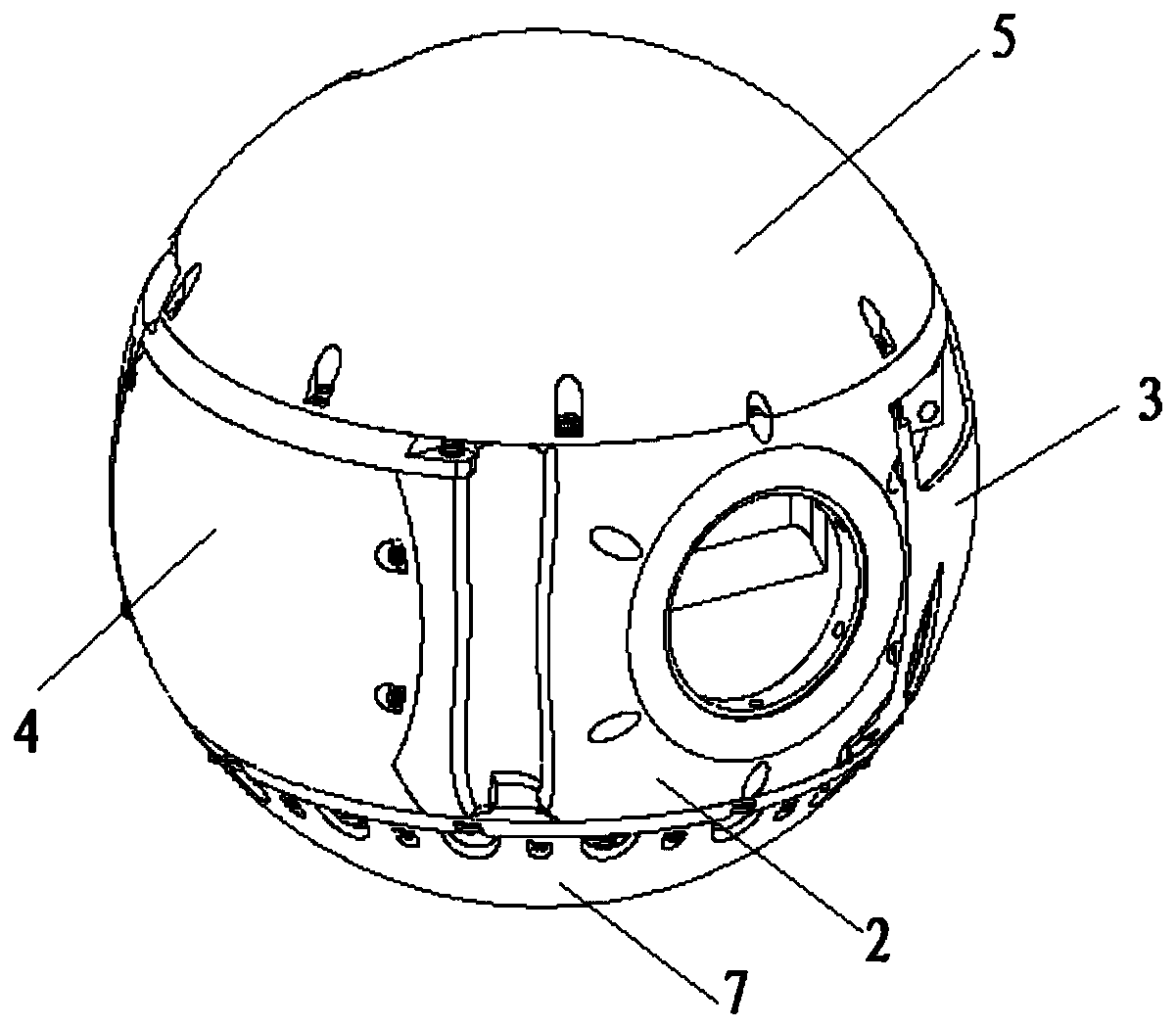
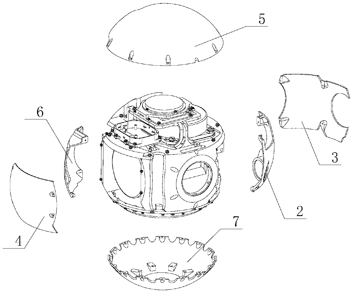
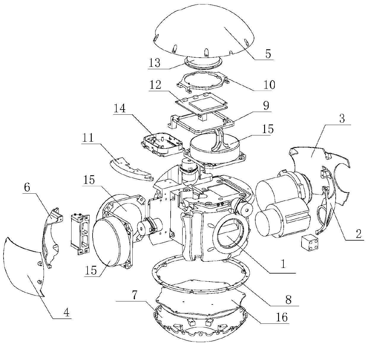
A multi-functional structure of an inertial platform spherical platform body

An inertial platform, multi-functional technology, applied in the direction of navigation through speed/acceleration measurement, can solve the problems of occupying the surface installation space of the table, not equipped with fiber optic gyroscope, low space utilization, etc., to ensure the stability of the thermal environment of the instrument performance, improve the efficiency of distribution balance, and improve the effect of space utilization

Active Publication Date: 2020-05-12
BEIJING INST OF AEROSPACE CONTROL DEVICES
View PDF4 Cites 0 Cited by
  • Summary
  • Abstract
  • Description
  • Claims
  • Application Information

AI Technical Summary

Problems solved by technology

The traditional platform body is not wrapped by a shell, and the thermal environment stability is poor; the structure of the body is rectangular, the turning space is cylindrical, and the space utilization rate is low; the circuit board is directly installed on the body without transition pieces, and the disassembly process is poor, occupying A large amount of surface installation space; the traditional inertial platform does not have an optical fiber routing structure, and does not have the ability to equip an optical fiber gyroscope; the trimming of the traditional inertial platform depends on repeated processing and grinding of lead weights, which is inefficient

Method used


Image

  • A multi-functional structure of an inertial platform spherical platform body
  • A multi-functional structure of an inertial platform spherical platform body
  • A multi-functional structure of an inertial platform spherical platform body

Examples


Embodiment Construction

[0024] Below in conjunction with accompanying drawing and specific embodiment the present invention is described in further detail:

[0025] The difference between the multifunctional structure of the spherical platform of the inertial platform provided by the present invention and the rectangular platform assembly structure of the traditional inertial platform is that: in the multifunctional structure of the spherical platform of the present invention, the spherical platform 1 and the six spherical shells form a complete The spherical structure has higher structural stability than the traditional open rectangular platform structure. At the same time, in the present invention, the six shells have the functions of counterweight and heat preservation, and simultaneously increase the structural rigidity of the platform assembly.

[0026] Such as figure 1 Shown is the front view of the multifunctional structure of the spherical platform of the inertial platform, such as figure ...


PUM


Abstract

The invention discloses a multifunctional structure of a spherical platform body of an inertial platform and relates to the field of the platform body structure of the spherical inertial stabilizationplatform. The multifunctional structure comprises a spherical platform body, a gyroscope accelerometer servo loop board bracket, a gyroscope digital circuit board bracket, a gyroscope interface circuit board bracket, an erbium-doped optical-fiber light source component bracket, a gyroscope digital circuit board, a gyroscope interface circuit board, an erbium-doped optical-fiber light source component, 3 optical-fiber gyroscopes and a gyroscope accelerometer servo loop board, wherein the 3 optical-fiber gyroscopes are respectively and fixedly arranged on the side wall of the spherical platformbody; the gyroscope accelerometer servo loop board and the gyroscope accelerometer servo loop board bracket are fixedly arranged at the bottom part of the spherical platform body; the gyroscope interface circuit board, the gyroscope interface circuit board bracket, the gyroscope digital circuit board, the gyroscope digital circuit board bracket, the erbium-doped optical-fiber light source component and the erbium-doped optical-fiber light source component bracket are respectively and fixedly arranged at the top part of the spherical platform body. The invention provides a novel installation mode of a platform body circuit of the inertial platform, provides a routing mode of light-signal transmission and improves a mode of balancing the components of the platform body.

Description

technical field [0001] The invention relates to the field of a platform body structure of a spherical inertial stable platform, in particular to a multifunctional structure of a spherical platform body of an inertial platform. Background technique [0002] The main function of the gyro-stabilized platform is to establish a navigation coordinate system that has nothing to do with the angular motion of the projectile (arrow) according to the given technical indicators, and provide the necessary coordinate reference for the measurement of acceleration and attitude angle. , the platform assembly of the inertial platform is a device that is stable relative to the inertial coordinate system, providing a stable inertial space for the inertial instrument. The traditional platform body is not wrapped by a shell, and the thermal environment stability is poor; the structure of the body is rectangular, the turning space is cylindrical, and the space utilization rate is low; the circuit ...

Claims


Application Information

Patent Timeline
Patent Type & Authority Patents(China)
IPC IPC(8): G01C21/18
CPCG01C21/18
Inventor 岑志轩徐峰涛刘奇刘昀王文璞
Owner BEIJING INST OF AEROSPACE CONTROL DEVICES
Why Eureka
Try Eureka