
Crane, device and method for deflecting forces on crane

一种起重机、力元件的技术,应用在力的装置领域,能够解决维修强度大、复杂液压供给源、主动液压缸重等问题,达到节省成本、省略维护工作和控制工作、降低构建难度的效果

Inactive Publication Date: 2017-09-26
TEREX GLOBAL GMBH
View PDF7 Cites 1 Cited by
  • Summary
  • Abstract
  • Description
  • Claims
  • Application Information

AI Technical Summary

Problems solved by technology

Active hydraulic cylinders are heavy, especially compared to anchor rods, require control or adjustment, are prone to failure, are costly and repair intensive
Active hydraulic cylinders also require complex hydraulic supply sources

Method used


Image

  • Crane, device and method for deflecting forces on crane
  • Crane, device and method for deflecting forces on crane
  • Crane, device and method for deflecting forces on crane

Examples


Embodiment Construction

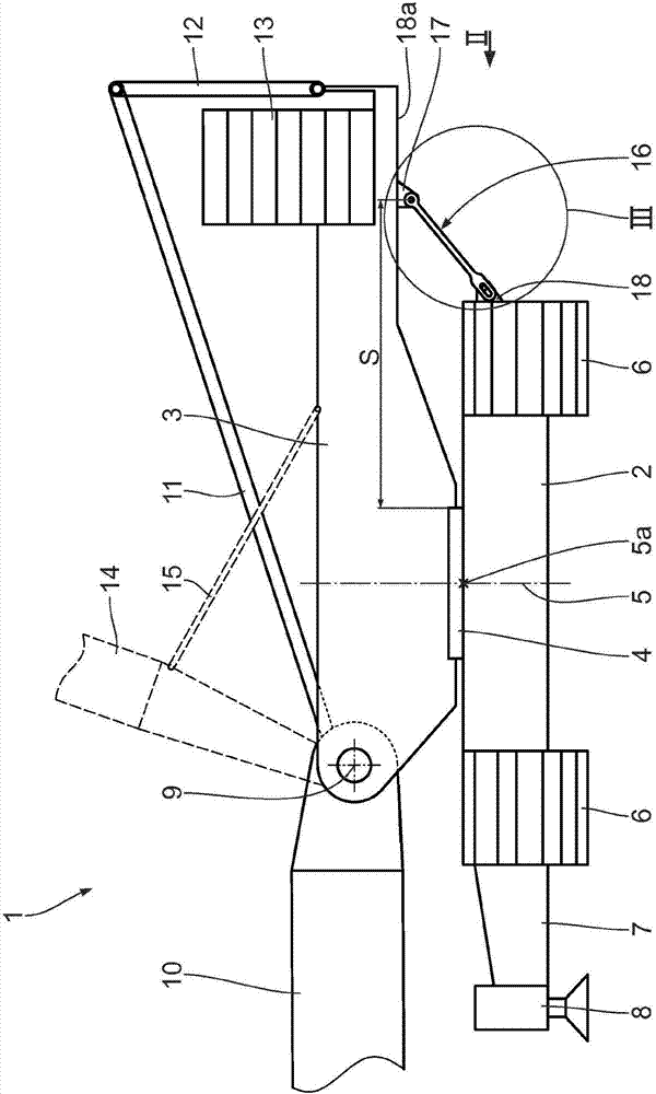
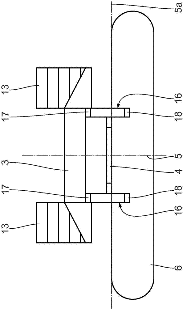
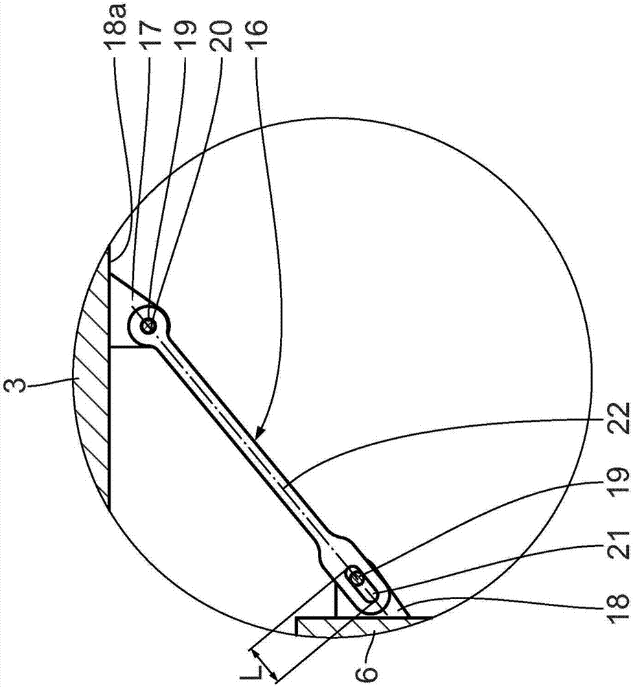
[0058] Figure 1 to 3 The illustrated embodiment relates to a crane 1 having a base frame 2, an upper frame 3 and a rotary connection 4, the upper frame 3 is rotatably connected to the base frame 2 about a vertical rotation axis 5 by means of the rotary connection 4. The rotary connection 4 includes several rollers, not shown, which roll on a rotating ring. The rotating connection 4 is a roller bearing swivel. According to the illustrated embodiment, the main frame beam 6 is arranged on the underframe 2. Crane 1 is a crawler crane. The crane 1 can also be designed as a mobile crane or a pedestal crane. Mobile cranes are especially equipped with rubber tires. Pedestal cranes are usually supported on several bases or foundations. The pedestal crane is not movable.

[0059] in figure 1 On both sides of the frame main beam 6 shown on the left in the middle, two supporting main beams 7 are designed on the underframe 2, including a supporting cylinder 8 and / or a pressurizing spind...


PUM


Abstract

The invention relates to a crane comprising an undercarriage (2), a superstructure (3), a slewing connection (4) by means of which the superstructure (3) is connected to the undercarriage (2) so as to be rotatable about a slewing axis (5), a jib (10) which can be connected to the crane (1) and can be erected about a jib axis (9), and a device which connects the superstructure (3) to the undercarriage (2) and has at least one force-conducting element (16). The at least one force-conducting element is configured to be passive in such a way that it transmits forces between the superstructure (3) and the undercarriage (2) if a predetermined load state of the slewing connection (4) is reached.

Description

Technical field [0001] This application claims the priority of German patent application DE102014213724.1, the content of which is incorporated herein by reference. [0002] The invention relates to a crane, a device and a method for deflecting / offsetting the force on the crane. Background technique [0003] CN102745604A knows a crane with a boom / boom that can be raised. The cantilever is rotatably installed in the base on the upper frame of the crane. The cantilever is connected to an arm lifting device activated by means of a rope winding device in the head region for raising the arm. The linkage of the cantilever is eccentric with respect to the rotation axis of the rotating connection piece provided between the upper frame and the bottom frame of the crane. The anchor rod is bolted to the hole between the upper frame and the bottom frame designed for this purpose in order to avoid undesired loads on the rotating connection. The anchor rod enables the pulling force from the ...

Claims


Application Information

Patent Timeline
Patent Type & Authority Applications(China)
IPC IPC(8): B66C23/78
CPCB66C23/78B66C13/16B66C23/84
Inventor F-B·克斯特B·沙尔A·韦克贝克F·施尼特克尔
Owner TEREX GLOBAL GMBH
Learn More