Flexible wiring board
A wiring board, stretchable technology, applied in the direction of dielectric properties, elastic polymer dielectric, circuit bendable/stretchable parts, etc., can solve the problems affecting the operating voltage of electronic devices, reducing the action, etc., to achieve The effects of suppressing the decrease in operability, suppressing elongation, and suppressing the increase in resistance value
- Summary
- Abstract
- Description
- Claims
- Application Information
AI Technical Summary
Problems solved by technology
Method used
Image
Examples
no. 1 approach
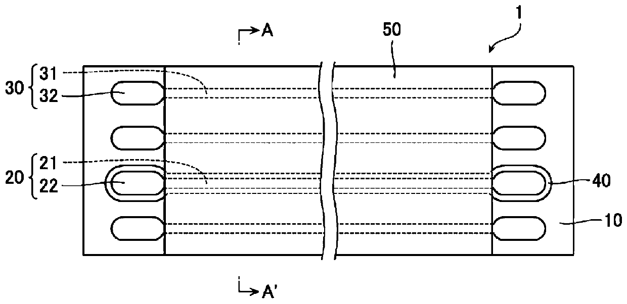
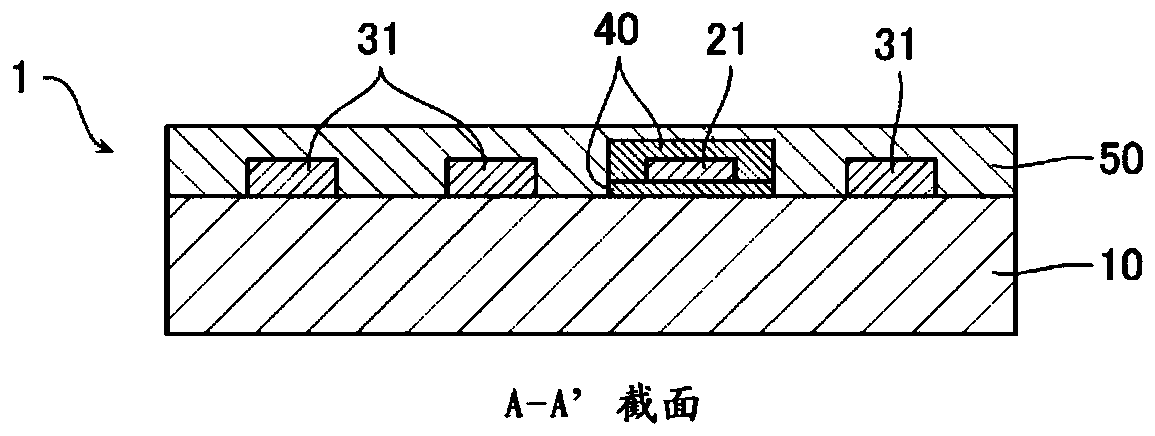
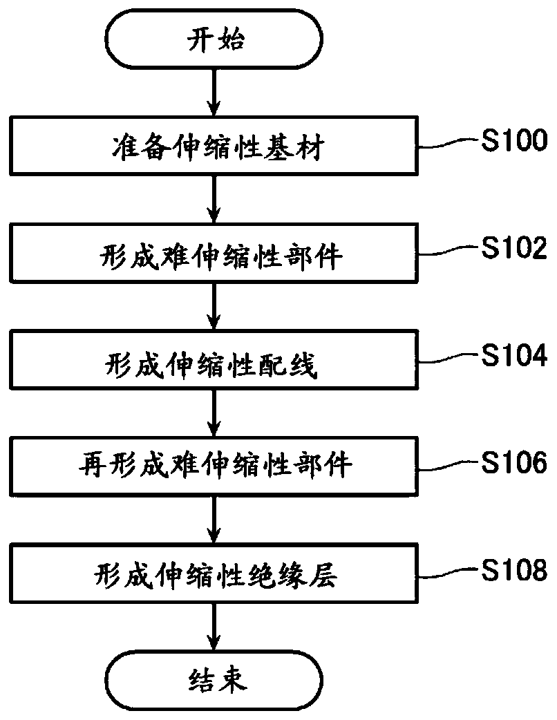
[0032] figure 1 It is a plan view showing the stretchable wiring board 1 according to the first embodiment of the present invention, figure 2 yes figure 1 The A-A' line sectional view. in addition, image 3 It is a flowchart showing the manufacturing process of the stretchable wiring board 1 .
[0033] Such as figure 1 with figure 2 As shown, the stretchable wiring board 1 according to the first embodiment includes a stretchable base material 10 and a plurality of first stretchable wirings 20 and second stretchable wirings arranged side by side on the stretchable base material 10 . Line 30. In addition, the stretchable wiring board 1 includes a hardly stretchable member 40 that overlaps, for example, the region where the first stretchable wiring 20 is formed in its thickness direction in plan view of the stretchable base material 10 . . Furthermore, the stretchable wiring board 1 includes a stretchable insulating layer 50 formed to cover, for example, the wiring port...
no. 2 approach
[0065] Figure 4 It is a plan view showing the stretchable wiring board 1A according to the second embodiment of the present invention, Figure 5 yes Figure 4 The B-B' line sectional view. exist Figure 4 with Figure 5 , for the first embodiment ( Figure 1 ~ Figure 2 ) The same constituent elements are marked with the same reference signs, and repeated explanations are omitted below.
[0066] Such as Figure 4 with Figure 5 As shown, in the stretchable wiring board 1A according to the second embodiment, the hardly stretchable member 40 is not provided in the region where the electrode terminal portion 22 of the first stretchable wiring 20 is formed. In addition, the hard-to-stretch member 40 is not provided in the portion between the stretchable base material 10 and the wiring portion 21 . In these two points, the stretchable wiring board 1A of the second embodiment is different from the stretchable wiring board 1 of the first embodiment.
[0067]That is, in the s...
no. 3 approach
[0069] Image 6 It is a plan view showing the stretchable wiring board 1B according to the third embodiment of the present invention, Figure 7 yes Image 6 The C-C' line section view. exist Image 6 with Figure 7 , for the second embodiment ( Figure 4 ~ Figure 5 ) The same constituent elements are marked with the same reference signs, and repeated explanations are omitted below.
[0070] Such as Image 6 with Figure 7 As shown, in the stretchable wiring board 1B according to the third embodiment, the hard-to-stretch member 40 only overlaps with the formation region of the wiring portion 21 of the first stretchable wiring 20 in the thickness direction in plan view. , does not overlap with the formation region of the electrode terminal portion 22, which is the same as the stretchable wiring board 1A of the second embodiment.
[0071] However, in the stretchable wiring board 1B according to the third embodiment, the hardly stretchable member 40 is formed on the surfac...
PUM
 Abstract
Description
Claims
Application Information
 - R&D
- Intellectual Property
- Life Sciences
- Materials
- Tech Scout
- Unparalleled Data Quality
- Higher Quality Content
- 60% Fewer Hallucinations
Browse by: Latest US Patents, China's latest patents, Technical Efficacy Thesaurus, Application Domain, Technology Topic, Popular Technical Reports.
© 2025 PatSnap. All rights reserved.Legal|Privacy policy|Modern Slavery Act Transparency Statement|Sitemap|About US| Contact US: help@patsnap.com


