
Sphygmomanometer

A sphygmomanometer and manometer technology, applied in the field of sphygmomanometer, can solve the problems of affecting the accuracy of measurement results, inconvenient operation, etc., and achieve the effects of saving measurement time, improving accuracy and powerful functions

Inactive Publication Date: 2017-09-29
HEFEI TONGYOU ELECTRONICS TECH CO LTD
View PDF3 Cites 0 Cited by
  • Summary
  • Abstract
  • Description
  • Claims
  • Application Information

AI Technical Summary

Problems solved by technology

The measurer uses a stethoscope to listen to the beating sound of the pulse to judge the systolic and diastolic blood pressure. During the process of hearing the beating sound of the pulse, the measurer needs to observe the dial of the sphygmomanometer or the blood pressure value on the display screen with the naked eye to record the measured blood pressure. Systolic blood pressure and diastolic blood pressure, for those who have not received professional training, there are many inconveniences in the operation, and directly affect the accuracy of the measurement results

Method used


Image

  • Sphygmomanometer
  • Sphygmomanometer
  • Sphygmomanometer

Examples


Embodiment Construction

[0027] The technical solutions of the present invention will be clearly and completely described below in conjunction with the accompanying drawings of the present invention. Reference will now be made in detail to the exemplary embodiments, examples of which are illustrated in the accompanying drawings. When the following description refers to the accompanying drawings, the same numerals in different drawings refer to the same or similar elements unless otherwise indicated. The implementations described in the following exemplary examples do not represent all implementations consistent with the present invention. Rather, they are merely examples of apparatuses and methods consistent with aspects of the invention as recited in the appended claims.

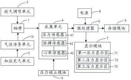
[0028] Such as figure 1 As shown, a sphygmomanometer of this embodiment includes: a cuff 1, a pressurized inflation unit 2, a deflation adjustment unit 3, an acquisition unit 4, a storage module 6, a microprocessor 5, a power sup...


PUM


Abstract

The invention discloses a sphygmomanometer. The sphygmomanometer comprises a cuff, a pressurizing and inflating unit, a deflating and adjusting unit, an acquiring unit, a storage module, a microprocessor, a power supply, a pressure locking module and a display module, wherein the acquiring unit comprises a pressure sensor and a pulse sensor, the pressure sensor is used for acquiring pressure in the cuff and transmitting a pressure signal to the microprocessor; the pulse sensor is used for detecting pulse wave and determining initial pressure of heartbeat every time; when the pressure locking module is pushed, the pressure sensor acquires an initial pressure value of the heartbeat at present; the microprocessor is used for transmitting initial pressure values, which are acquired by the pressure sensor, of pressure and heartbeat and transmitting the initial pressure values to the storage module; and a pressure value is calculated by analysis. By the sphygmomanometer, the pressure value can be accurately measured in an inflating and compressing process; by pressure locking and heart rate measurement, functions are powerful; the structure is simple; and the sphygmomanometer caters for detection habits of a user.

Description

technical field [0001] The invention relates to the field of sphygmomanometers, in particular to a pressure gauge with a pressure locking function and capable of shortening measurement time. Background technique [0002] With the aggravation of the population aging problem, family medical monitoring has a wider and wider market. As an important physiological parameter reflecting the state of the cardiovascular system and heart, blood pressure has become an important content of family medical monitoring. Although traditional mercury sphygmomanometers are considered the gold standard for measuring blood pressure, electronic sphygmomanometers have received widespread attention because they require training and are inconvenient to carry. [0003] Most of the existing hand-held electronic sphygmomanometers currently use the Keshi sound method for blood pressure measurement to replace mercury sphygmomanometers. The measurer uses a stethoscope to listen to the beating sound of th...

Claims


Application Information

Patent Timeline
IPC IPC(8): A61B5/0225
Inventor 李丹丹
Owner HEFEI TONGYOU ELECTRONICS TECH CO LTD
Learn More