Sleeving device for tank

A tank body and mounting plate technology, which is applied in the field of tank body making tooling, can solve the problems of concentricity and difficulty in control when relying on crane hoisting and fitting, and achieves the effect of avoiding crane hoisting and ensuring fitting quality.

Active Publication Date: 2017-09-29
NANTONG CIMC ENERGY EQUIP CO LTD
View PDF10 Cites 3 Cited by
  • Summary
  • Abstract
  • Description
  • Claims
  • Application Information

AI Technical Summary

Problems solved by technology

[0005] The purpose of the present invention is to provide a tank fitting device, which solves the problems in the prior art that the inner container and the outer cylinder of the tank rely on driving and lifting and the concentricity is difficult to control when fitting.

Method used


Image

  • Sleeving device for tank
  • Sleeving device for tank
  • Sleeving device for tank

Examples


Embodiment Construction

[0029] Typical embodiments that embody the features and advantages of the present invention will be described in detail in the following description. It should be understood that the present invention is capable of various changes in different embodiments without departing from the scope of the present invention, and that the description and illustrations therein are illustrative in nature and not limiting. this invention.

[0030] The invention provides a can fitting device, which is used for fitting the outer cylinder of the can onto the inner container of the can.

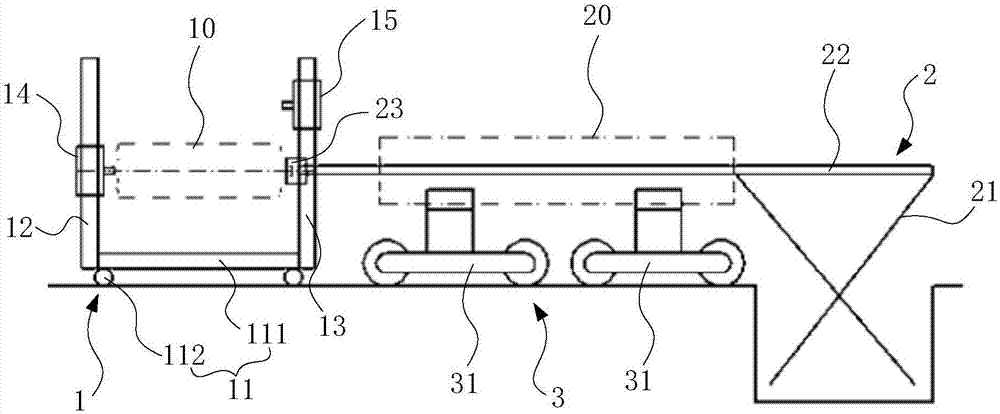
[0031] refer to figure 1 , the tank fitting device mainly includes a supporting device 1 , a cantilever device 2 and a conveying device 3 .

[0032] The supporting device 1 is used for supporting both ends of the inner container 10 and transporting the inner container 10 to the nesting station, and the conveying device 3 is used for supporting and transporting the outer cylinder 20 . When the inner container ...


PUM


Abstract

The invention provides a sleeving device for a tank. The sleeving device for the tank is used for sleeving an inner container of the tank with an outer cylinder of the tank. The sleeving device for the tank comprises supporting equipment, cantilever equipment and conveying equipment. The supporting equipment comprises a traveling trolley, two portal frames arranged on the traveling trolley in a spaced mode, and supporting mechanisms arranged on the portal frames in a lifting mode and used for supporting the ends of the inner container. The supporting equipment can move to a sleeving station through the travelling trolley. The cantilever equipment comprises a support, a supporting arm which is mounted on the support and stretches out of the support, and a supporting head which is movably arranged at the tail end of the supporting arm and used for supporting one end of the inner container. The supporting arm is long enough to be sleeved with the outer cylinder. The supporting head faces the sleeving station and can be used for supporting one end of the inner container when the inner container is located on the sleeving station. The conveying equipment can support and convey the outer cylinder, and the outer cylinder is conveyed to the sleeving station from the supporting arm so as to be arranged on the inner container in a sleeving mode. By adoption of the sleeving device for the tank, hoisting through a crane can be avoided, and the sleeving quality of the tank is improved.

Description

technical field [0001] The invention relates to tooling for tank body production, in particular to a tank body fitting device. Background technique [0002] The current tank body is generally mainly composed of an inner container and an outer shell that fits outside the inner container. When making the tank body, it is necessary to fit the cylinder of the outer shell (abbreviated as the outer tube) on the inner container. In the prior art, when the outer cylinder fits on the inner container, one end of the inner container is inserted into the outer cylinder by crane hoisting, and the outer cylinder is pre-set with a temporary track for fitting and an adapted The sliding trolley, the temporary track is placed inside the outer cylinder, and the head end of the inner container is fixed on the sliding trolley. When the driving car slowly sends the inner container into the outer cylinder, the sliding trolley plays the role of moving and supporting the inner container until the i...

Claims


Application Information

Patent Timeline
Patent Type & Authority Applications(China)
IPC IPC(8): B21D51/18
CPCB21D51/18
Inventor 毛志刚卫晓峰崔洪鹏吴军印金伟
Owner NANTONG CIMC ENERGY EQUIP CO LTD
Why Eureka
Try Eureka