
Ternary twisted groove end face mechanical seal structure

A kind of end face mechanical seal and mechanical seal technology, applied in the direction of engine seal, mechanical equipment, engine components, etc., can solve the problems of insufficient rigidity of fluid film, large seal leakage, large rigidity of fluid film, etc., and achieve strong diversion effect , Strengthen the compression effect, and the effect of low leakage rate

Active Publication Date: 2018-11-13
ZHEJIANG UNIV OF TECH
View PDF3 Cites 2 Cited by
  • Summary
  • Abstract
  • Description
  • Claims
  • Application Information

AI Technical Summary

Problems solved by technology

[0004] In order to improve the fluid film rigidity of the existing equal-depth or variable-depth typical spiral groove mechanical end seals under medium and high speed conditions, the fluid film rigidity is not large enough, and the seal leakage is relatively large. High rigidity, small leakage, ternary twisted groove mechanical end face seal structure suitable for medium and high speed operating conditions

Method used


Image

  • Ternary twisted groove end face mechanical seal structure
  • Ternary twisted groove end face mechanical seal structure
  • Ternary twisted groove end face mechanical seal structure

Examples


Embodiment 1

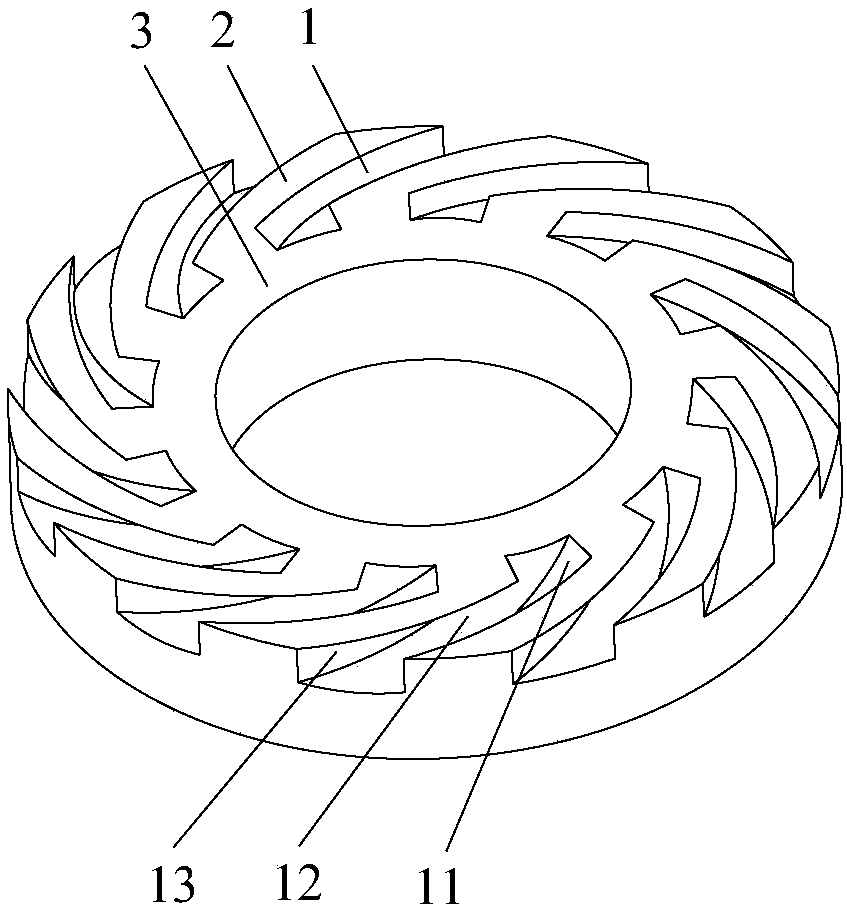
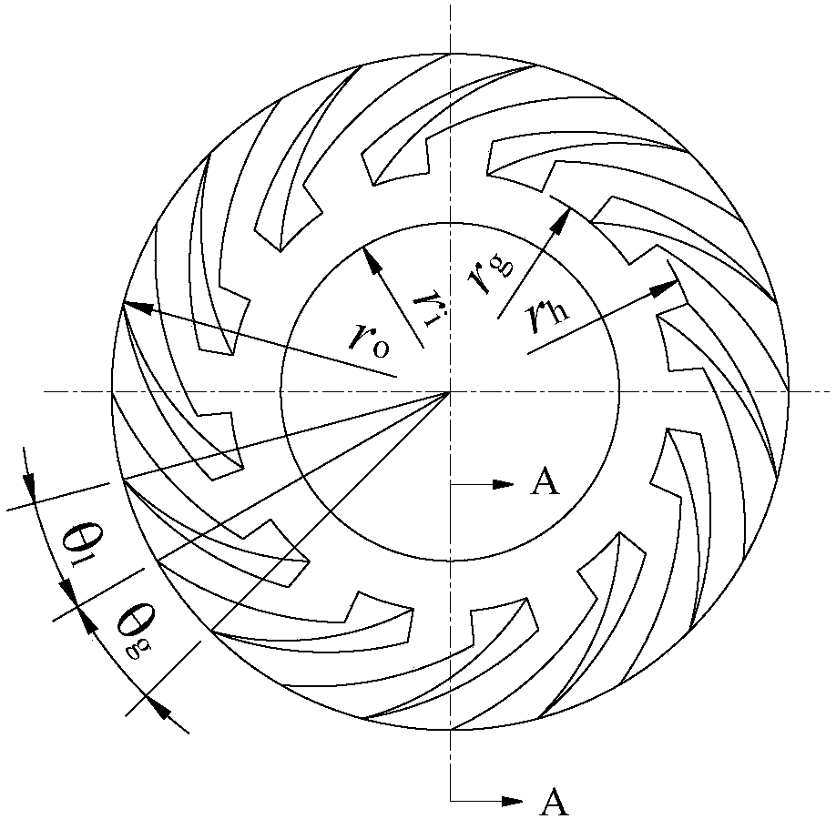
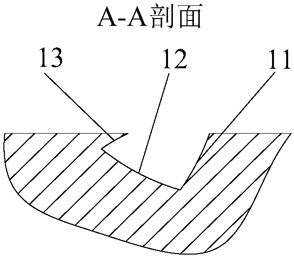
[0025] see figure 1 , 2 , 3 and 4, a ternary twisted groove end face mechanical seal structure, including a moving ring and a static ring of a mechanical seal, at least one of the sealing rings in the moving ring and the static ring is processed with seals evenly distributed along the circumference Three-dimensional twisted groove 1, the three-dimensional twisted groove 1 is composed of a three-dimensional twisted wall surface 11 on the windward side, a three-dimensional twisted wall surface 13 on the leeward side, and a three-dimensional twisted deep groove bottom surface 12; the side wall of the three-dimensional twisted groove 1 Including the three-dimensional twisted wall surface 11 on the windward side and the three-dimensional twisted wall surface 13 on the leeward side, the bottom surface 12 of the three-dimensional twisted deep groove gradually becomes shallower in a twisted shape from the outer peripheral side wall of the sealing ring to the center of the sealing ring...

Embodiment 2

[0032] see figure 1 , 2 , 3 and 4, the difference between this embodiment and Embodiment 1 is: the intersecting line of the medium inlet side in the intersection line between the side wall of the three-dimensional twisted groove 1 and the sealing end surface, that is, the three-dimensional twisted wall surface 11 on the windward side and the sealing end surface The intersection line 113 on the leakage port side and the intersection line 133 between the ternary twisted wall surface 13 on the leeward side and the medium inlet side of the sealing end surface are logarithmic helical lines. At the same time, the projection line of the intersection line 112 of the three-dimensional twisted wall surface 11 on the windward side and the bottom surface 12 of the three-dimensional twisted deep groove on the sealing end surface, and the intersection line 132 of the three-dimensional twisted wall surface 13 on the leeward side and the bottom surface 12 of the three-dimensional twisted deep...

Embodiment 3

[0036] refer to Figure 5 , 6 The difference between this embodiment and Embodiment 1 is that the projection line of the intersection line 112 of the three-dimensional twisted wall surface 11 on the leeward side and the bottom surface 12 of the three-dimensional twisted deep groove on the sealing end surface is a straight line, and the three-dimensional twisted wall surface on the windward side The projection line of the intersection line 132 of the element twisted wall surface 13 and the three-dimensional twisted deep groove wall surface 12 on the sealing end surface is a straight line; the intersection line 113 of the three-dimensional twisted wall surface 11 on the leeward side and the medium inlet side of the sealing end surface is a straight line, and the The intersection line 133 between the three-dimensional twisted wall surface 13 on the windward side and the medium inlet side of the sealing end surface is a straight line.


PUM


Abstract

A ternary distortion-type groove end surface mechanical sealing structure comprises a dynamic ring and a static ring which are used for mechanical sealing, ternary distortion-type grooves 1 evenly distributed in the circumferential direction are machined in the sealing end surface of at least one sealing ring of the dynamic ring and the static ring, and each ternary distortion-type groove is formed by two side walls and a three-dimensional distortion variable-depth groove bottom surface; the side walls of each ternary distortion-type groove comprise the windward side ternary distortion wall surface 11 and the leeward side ternary distortion wall surface 13, and the three-dimensional distortion variable-depth groove bottom surfaces 12 gradually shallow in a distortion shape from the outer circumferential side walls of the sealing rings to the centers of the sealing rings and intersect with the sealing end surfaces on the outer sides of sealing dams 3; the intersection lines of the side walls of the ternary distortion-type grooves 1 and the outer circumferential side walls of the sealing rings are perpendicular to the sealing end surfaces; the intersection lines of the side walls of the first ternary distortion-type grooves and the sealing end surfaces are each divided into two sections, the intersection lines on the medium inlet sides are helical lines, and the intersection lines on the medium leakage sides are radial straight lines.

Description

technical field [0001] The invention relates to a mechanical end face sealing structure for a shaft end of a rotary fluid machine, in particular to a mechanical end face sealing structure of a three-dimensional twisted groove whose wall surface is a three-dimensional twisted surface, which is used for various compressors, pumps and Rotary shaft seals for rotating machines such as reactors. Background technique [0002] The gas-lubricated or liquid-lubricated non-contact mechanical seal with equal-depth spiral groove structure on the sealing end face has been widely used in medium and high-speed rotating machinery (such as centrifugal compressors, high-speed pumps, etc.) in petroleum, petrochemical and electric power industries. When the moving ring rotates, the fluid medium is pumped into the sealing end surface by using the dynamic and static pressure effect of the groove, the fluid medium entering the sealing end surface is blocked from flowing at the root of the groove an...

Claims


Application Information

Patent Timeline
Patent Type & Authority Patents(China)
IPC IPC(8): F16J15/16
CPCF16J15/16
Inventor 彭旭东江锦波孟祥铠陈源李纪云
Owner ZHEJIANG UNIV OF TECH
Learn More