

Test method, device and electronic equipment
A technology of electronic equipment and test method, applied in the field of testing, can solve the problems of poor generality of test methods, and achieve the effect of realizing control test and improving generality
- Summary
- Abstract
- Description
- Claims
- Application Information
AI Technical Summary
Problems solved by technology
Method used
Image

Examples
Embodiment 1
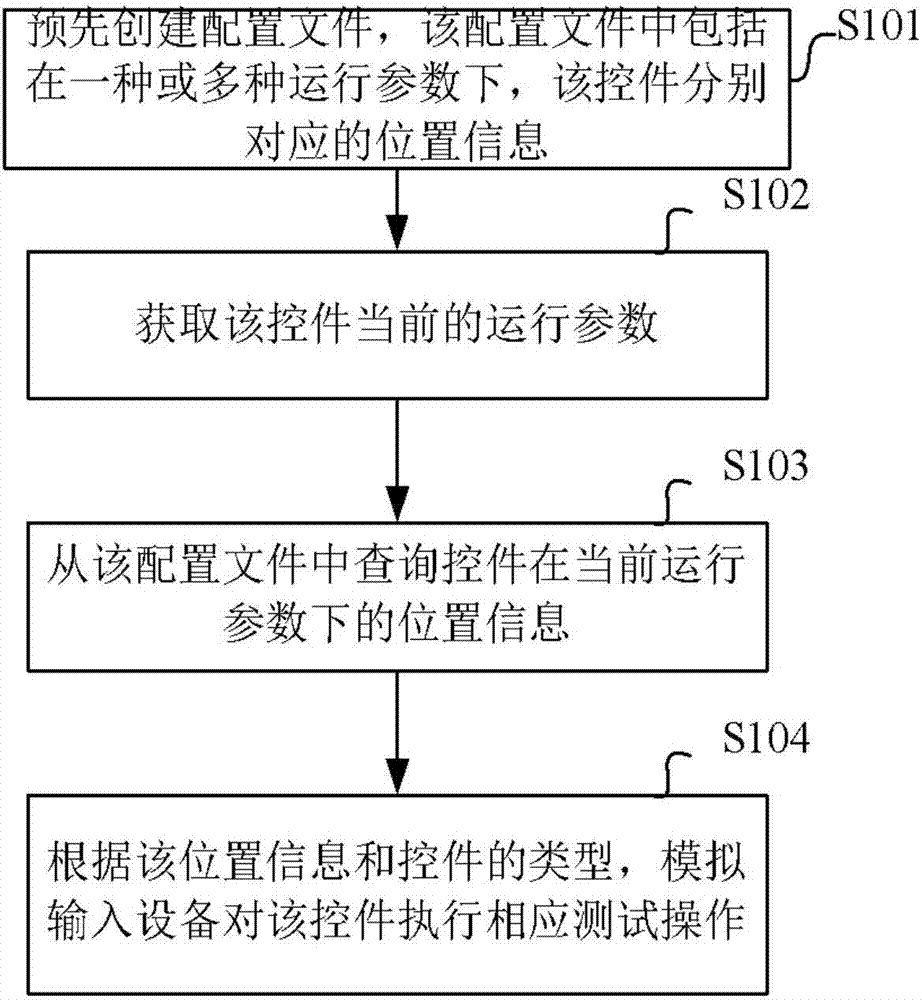
[0024] figure 1 It is a flow chart of the test method in Example 1 of the present application. Such as figure 1 As shown, the test method according to the first embodiment of the application comprises the following steps:
[0025] S101, create a configuration file in advance, the configuration file includes position information corresponding to the control under one or more operating parameters, and the position information is used to identify the corresponding position of the control when it is displayed on the display screen of the electronic device Location;
[0026] S102, acquiring the current operating parameters of the control;
[0027] S103, query the position information of the control under the current operating parameters from the configuration file;
[0028] S104. According to the location information and the type of the control, the simulated input device performs a corresponding test operation on the control.
[0029] During specific implementation, in a spec...
Embodiment 2
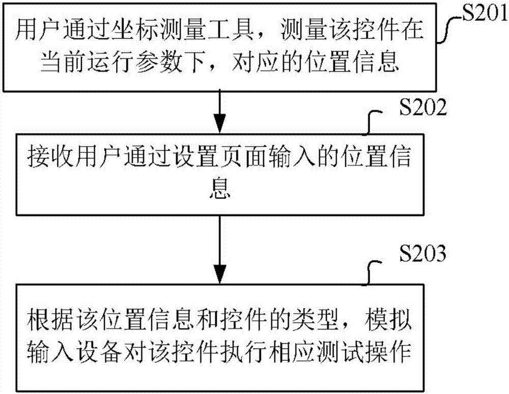
[0081] figure 2 It is a flow chart of the testing method shown in Example 2 of the present application.
[0082] Such as figure 2 As shown, according to the test method shown in Embodiment 2 of the present application, the test method comprises the following steps:
[0083] S201, the user uses a coordinate measurement tool to measure the corresponding position information of the control under the current operating parameters;
[0084] S202. Receive location information input by the user through the setting page;
[0085] S203. According to the location information and the type of the control, the simulated input device performs a corresponding test operation on the control.
[0086] During specific implementation, the location information may include coordinate information of the control on the screen. Specifically, the coordinate information can be based on the upper left corner of the screen as the origin, the positive direction of the x-axis is horizontally to the rig...
Embodiment 3
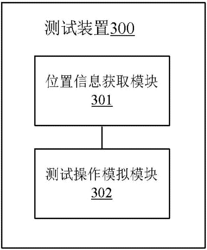
[0097] image 3 It is a schematic structural diagram of the test device shown in Example 3 of the present application.
[0098] Such as image 3 As shown, according to the third embodiment of the present application, the test device 300 includes: a location information acquisition module 301, configured to acquire the location information of the control, and the location information is used to identify that the control is displayed on the display screen of the electronic device the corresponding position; the test operation simulation module 302 is configured to simulate the input device of the electronic device to perform a corresponding test operation on the control according to the position information and the type of the control.
[0099] During specific implementation, the location information acquisition module may specifically be used to: read the location information of the control from a pre-created configuration file; or measure the location information of the contr...
PUM
 Abstract
Description
Claims
Application Information