Heat dissipation structure for electric welding machine

A technology of heat dissipation structure and electric welding machine, which is applied in the direction of welding accessories, etc., can solve the problems of poor heat dissipation effect and complex structure, and achieve the effect of improving heat dissipation effect and good heat dissipation effect

Inactive Publication Date: 2017-10-03
鄢贵龙
View PDF1 Cites 2 Cited by
  • Summary
  • Abstract
  • Description
  • Claims
  • Application Information

AI Technical Summary

Problems solved by technology

[0003] The technical problem to be solved by the present invention is to provide a heat dissipation structure for an electric welding machine, which can solve the problem that the heat dissipation structure of the existing inverter welding machine uses three heat sinks to form a door frame-shaped air duct, and the fins on the heat sink will form a certain obstruction effect on the wind Form a dead zone, resulting in poor heat dissipation and complex structure

Method used


Image

  • Heat dissipation structure for electric welding machine
  • Heat dissipation structure for electric welding machine

Examples


Embodiment Construction

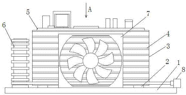
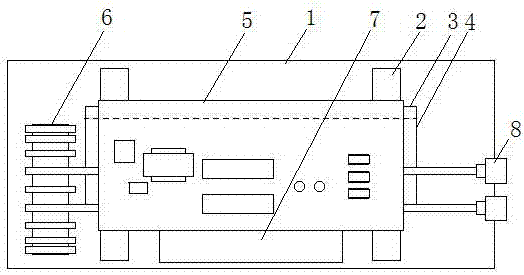
[0014] Such as figure 1 and figure 2 The shown heat dissipation structure of an electric welding machine includes a bottom plate 1 of the electric welding machine, a control circuit board 5, a transformer 6 and a fan 7, and also includes an aluminum substrate 3 whose bottom end is vertically installed on the bottom plate 1 through a ceramic or silica gel isolation pad 2 , the front of the aluminum substrate 3 is provided with multi-layer horizontal aluminum heat sinks 4, the aluminum substrate 3 and the aluminum heat sink 4 are integrally formed, the control circuit board 5 is connected to the upper surface of the top aluminum heat sink 4, The transformer 6 is arranged on one side of the aluminum heat sink 4 , the terminal 8 of the transformer 6 extends to the other side of the aluminum heat sink, the fan 7 is arranged in the front middle of the aluminum substrate 3 , and the air outlet faces the aluminum substrate 3 .


PUM


Abstract

The invention discloses a heat dissipation structure of an electric welding machine, which includes a bottom plate of the electric welding machine, a control circuit board, a transformer and a fan, and an aluminum base plate vertically installed on the bottom plate. The control circuit board is connected to the upper surface of the top aluminum heat sink, the transformer is arranged on one side of the aluminum heat sink, the terminals of the transformer extend to the other side of the aluminum heat sink, and the fan is arranged in front of the aluminum substrate In the middle, and the air outlet faces the aluminum substrate. Multiple air ducts are formed between the multi-layered horizontal aluminum heat sinks on the front of the aluminum base plate. The fan blows the wind from the middle of the front to the aluminum base plate, and then flows to both ends of the air duct respectively. There is no dead zone, and the stroke of the cold air is shortened by half. The heat dissipation effect will not be affected by the gradual increase in temperature; the transformer and its terminals are respectively arranged on both sides of the aluminum heat sink, and the wind flowing out of the air duct directly blows away the heat, and the heat dissipation effect is good.

Description

technical field [0001] The invention relates to the field of electric welding machines, in particular to a heat dissipation structure for electric welding machines. Background technique [0002] The electric welding machine uses the high-temperature arc generated when the positive and negative poles are short-circuited in an instant to melt the solder on the electrode and the material to be welded to achieve the purpose of combining them. Its basic structure is a high-power transformer, which can be combined with the control circuit board. To achieve more and more functions, since the transformer and the devices on the control circuit board will generate a lot of heat during use, a heat dissipation mechanism must be installed to prevent the heat from accumulating and causing the transformer or devices to burn out. The Chinese invention patent publication with the patent number 201020518186 A heat dissipation structure for an inverter welding machine is developed. Three heat ...

Claims


Application Information

Patent Timeline
Patent Type & Authority Applications(China)
IPC IPC(8): B23K9/32
CPCB23K9/32
Inventor 鄢贵龙
Owner 鄢贵龙
Why Eureka
Try Eureka