Light-emitting diode packaging structure and packaging method thereof

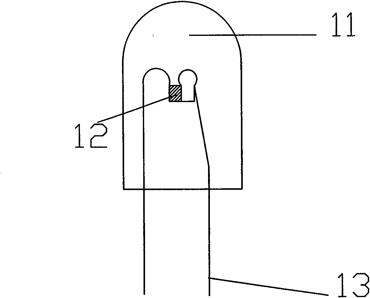
A technology of light-emitting diodes and packaging structures, which is applied in the direction of semiconductor devices, electrical components, circuits, etc., and can solve the problems of small heat transfer area of ​​metal bracket 13, difficult to achieve heat dissipation effect, poor thermal conductivity, etc., to achieve material saving and simple structure , Adaptable effect

Active Publication Date: 2013-10-23
SHENZHEN UNIV
View PDF0 Cites 0 Cited by
  • Summary
  • Abstract
  • Description
  • Claims
  • Application Information

AI Technical Summary

Problems solved by technology

Wherein the two electrodes of the SMD LED light-emitting chip are respectively connected on two metal supports, there are main problems as follows: 1), the thermal conductivity of the epoxy resin layer 11 is extremely poor, and the completely covered structure causes a large amount of heat in the LED light-emitting chip 12 stacking; 2), according to the thermal resistance calculation formula, R=h / λ*S (S is the heat flow area, h is the distance through which the heat flow passes, and λ is the thermal conductivity), the heat flow area of ​​the metal support 13 is too small and If the length is too large, it is difficult to achieve a good heat dissipation effect

Method used


Image

  • Light-emitting diode packaging structure and packaging method thereof
  • Light-emitting diode packaging structure and packaging method thereof
  • Light-emitting diode packaging structure and packaging method thereof

Examples


Embodiment 2

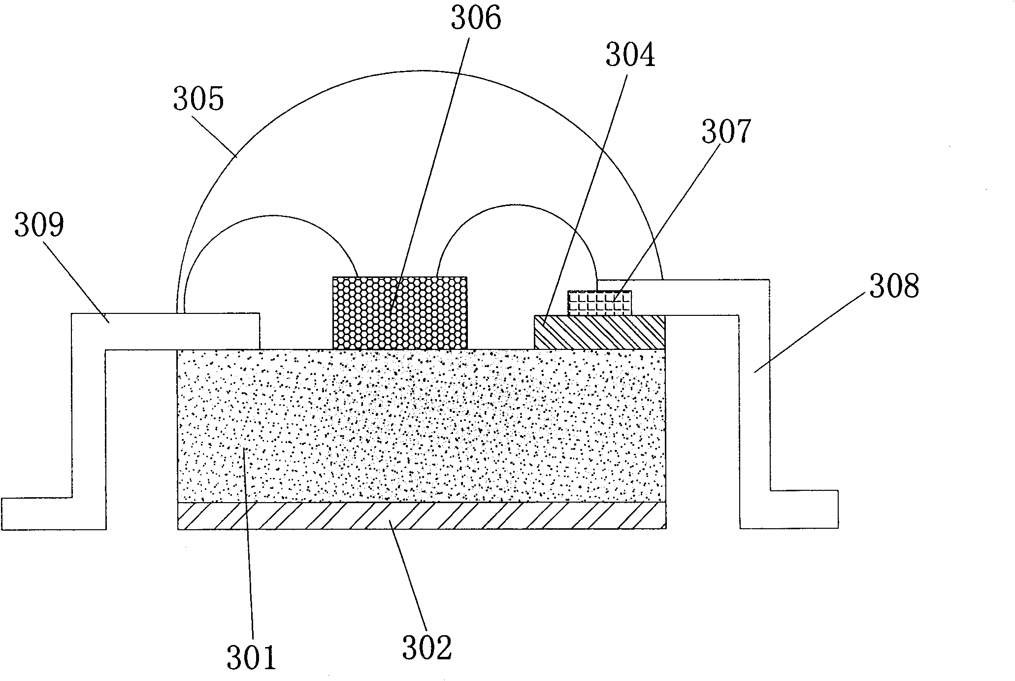
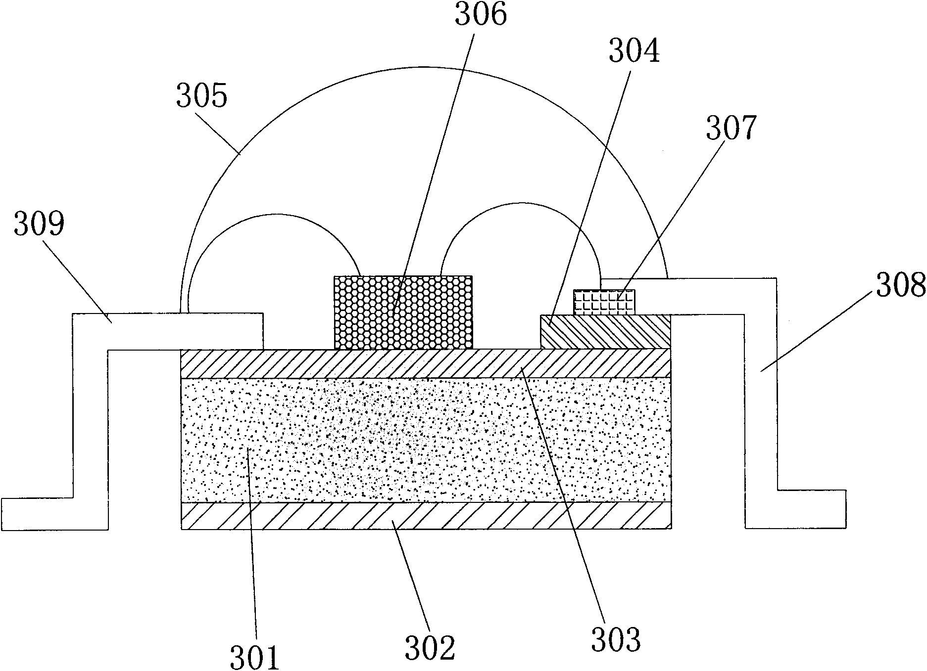
[0047] In Embodiment 2, the bottom of the metal substrate 301 is set as a rough bottom surface, and a layer of ceramic insulating layer (ie, the second insulating layer 302 ) is fabricated on the rough bottom surface of the bottom of the metal substrate by thermal spraying. In this embodiment, the first external electrode 308 and the second external electrode 309 are respectively welded on the metal electrode layer 307 and the metal heat conducting layer 303 by ultrasonic welding or resistance welding. The metal electrode layer 307 is melted and attached to the glass-ceramic insulating layer by means of laser ablation.

[0048] The laser ablation and melting method is used to form the required glass ceramic insulating layer and metal electrode layer, which avoids the overall high-temperature sintering, does not need to use a high-temperature sintering process, saves energy, is environmentally friendly, expands the types of optional metal substrate materials, and is easy to real...


PUM


Abstract

The invention relates to the field of optoelectronic packaging and discloses a light-emitting diode (LED) packaging structure and a packaging method thereof. The invention has the following beneficial effects: not passing through a ceramic insulating layer, an LED chip directly keeps away from the low heat conductivity bottleneck, and the heat can not be accumulated in the insulating layer; a metal heat conducting layer can rapidly transfer the heat generated by the LED chip to a metal substrate; the metal substrate has sufficient width and heat dissipation space; and a glass-ceramic insulating layer is manufactured on the metal heat conducting layer by selective laser melting and then a metal electrode layer and external electrodes are manufactured on the glass-ceramic insulating layer, thus not only ensuring insulation of the tube shell with the outside but also having little effect on the overall heat dissipation effect. The required ceramic insulating layer and the metal electrode layer are formed by laser ablation melting, thus avoiding overall high temperature sintering, dispensing with the high temperature sintering process, saving energy, protecting the environment, enlarging the material types of the selectable metal substrate and being easy to realize industrialization.

Description

technical field [0001] The invention relates to the field of optoelectronic packaging, in particular to a light emitting diode packaging structure and a packaging method thereof. Background technique [0002] The current shell structure of the light-emitting diode is mainly to install the patch-type light-emitting diode chip on the insulating substrate, and then install the electrodes on the circuit on the insulating substrate. The thermal conductivity of the LED is very poor, which becomes the bottleneck of heat dissipation, especially for high-power LEDs, the heat cannot be conducted quickly and accumulates in the LED light-emitting chip, resulting in a decrease in performance and life. [0003] Such as figure 1 The LED in the package is the current mainstream packaging mode, including an epoxy resin layer 11, a patch-type LED light-emitting chip 12, and a metal bracket 13. Wherein the two electrodes of the SMD LED light-emitting chip are respectively connected on two me...

Claims


Application Information

Patent Timeline
Patent Type & Authority Patents(China)
IPC IPC(8): H01L33/48H01L33/64
CPCH01L2224/48091H01L2224/48247H01L2224/49109H01L2924/181
Inventor 柴广跃雷云飞刘文黄长统王少华刘沛徐光辉
Owner SHENZHEN UNIV
Why Eureka
Try Eureka