Displacement adjusting and compensating device as well as rail system comprising displacement adjusting and compensating device
A technology of compensation device and displacement adjustment, which is applied in the direction of track, road, ballast layer, etc., can solve the problems that affect the quality and safety of the project and the use time, and there are no effective measures to completely cure it, so as to save engineering quantity, save production cost, The effect of simple tooling
- Summary
- Abstract
- Description
- Claims
- Application Information
AI Technical Summary
Problems solved by technology
Method used
Image
Examples
Embodiment 1
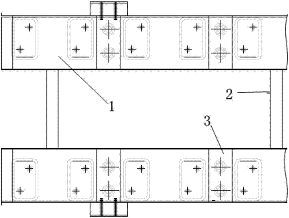
[0033] see Figure 1-4 , shows the displacement adjustment compensation device and the height-adjusting trapezoidal sleeper of the present invention, and the displacement adjustment compensation device is added on the basis of the existing trapezoidal sleeper structure. When prefabricating the trapezoidal sleeper structure, the displacement adjustment compensation device is embedded in the trapezoidal sleeper structure in advance to form a built-in height-adjusting trapezoidal sleeper system. It specifically includes trapezoidal sleeper longitudinal beams 1 , transverse steel pipes 2 connected between the longitudinal beams 1 and vibration damping pads 8 provided at the lower end of the longitudinal beams 1 , wherein a displacement adjustment compensation device 3 is arranged in the sleeper longitudinal beams 1 .
[0034] see Figure 4 , the main structure of the displacement adjustment compensation device includes a first support 6, a second support 5, a filler 9, and a bott...
Embodiment 2
[0043] see Figure 7 , 8 , shows the displacement adjustment and compensation device of Embodiment 2 of the present invention, its main structure includes a first support 6, a second support 5, a filler 9, a bottom plate 7, and a cover 14, wherein the first support 6 is a cylinder The upper and lower openings are closed by the cover plate 14, and the inner accommodating space is used to place the filler 9, and the size of the opening at the lower part of the first support member allows the filler to pass through. The lower part of the side wall of the first support member 6 has a groove, so that the section of the side wall 6 is formed as an inverted U shape, and the side wall is divided into an inner wall and an outer wall, and the tops of the inner wall and the outer wall are connected.
[0044]The second support member 5 is a structure that can be inserted into the groove of the side wall of the first support member 6, such as an annular structure, and can move along the d...
Embodiment 3
[0053] see Figure 9-11 , shows the displacement adjustment and compensation device according to Embodiment 3 of the present invention. The displacement adjustment and compensation device mainly includes a first support 6 , a second support 5 , a filler 9 , a top plate 4 , and a bottom plate 7 . The first support member 6 is a cylindrical structure, which has a space capable of accommodating fillers 9. The lower part of the space is provided with a bottom plate with an opening, and its upper part is connected with the top plate 4. The second support member 5 is connected with the bottom plate. Nested in the second support 5 . The filler can pass through the opening into the second support 5 .
[0054] see Figure 10 , the vibration isolator 12 is arranged in the vibration isolator sleeve 13 of the floating plate 11, the displacement adjustment compensating device 3 is arranged on the vibration isolator 12, and its top is connected with the floating 11 plate, which is used to...
PUM
 Abstract
Description
Claims
Application Information
 - R&D
- Intellectual Property
- Life Sciences
- Materials
- Tech Scout
- Unparalleled Data Quality
- Higher Quality Content
- 60% Fewer Hallucinations
Browse by: Latest US Patents, China's latest patents, Technical Efficacy Thesaurus, Application Domain, Technology Topic, Popular Technical Reports.
© 2025 PatSnap. All rights reserved.Legal|Privacy policy|Modern Slavery Act Transparency Statement|Sitemap|About US| Contact US: help@patsnap.com


