Engine intake manifold assembly and vehicle
A technology of engine and intake pipe, which is applied in the direction of engine components, machine/engine, and power plant gas intake, etc. It can solve the problems of inability to perform telescopic movement, large space occupation, and inability to absorb vibrations, etc., to save length and layout space , Improve the effect of shock absorption
- Summary
- Abstract
- Description
- Claims
- Application Information
AI Technical Summary
Problems solved by technology
Method used
Image
Examples
Embodiment Construction
[0027] Specific embodiments of the present disclosure will be described in detail below in conjunction with the accompanying drawings. It should be understood that the specific embodiments described here are only used to illustrate and explain the present disclosure, and are not intended to limit the present disclosure.
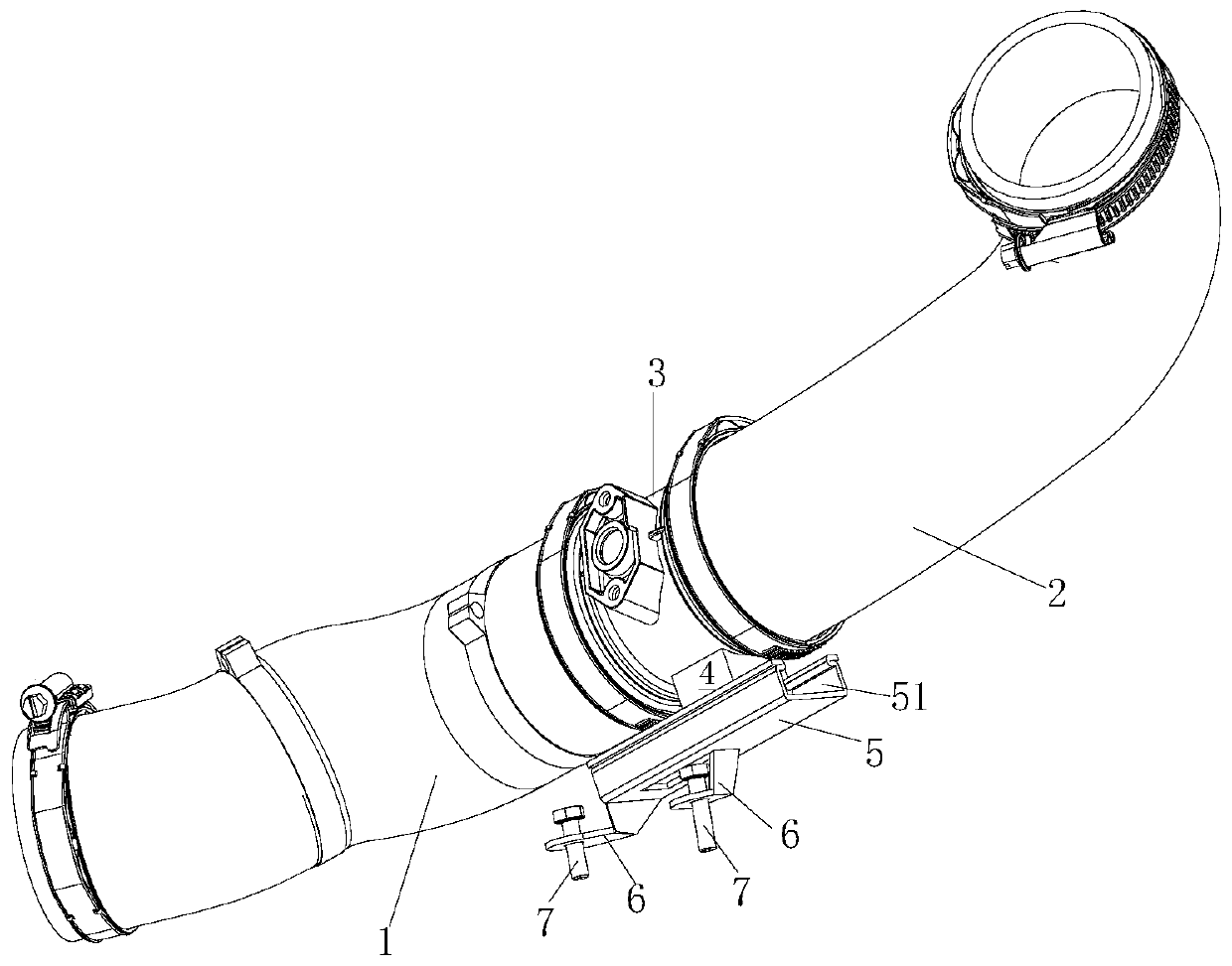
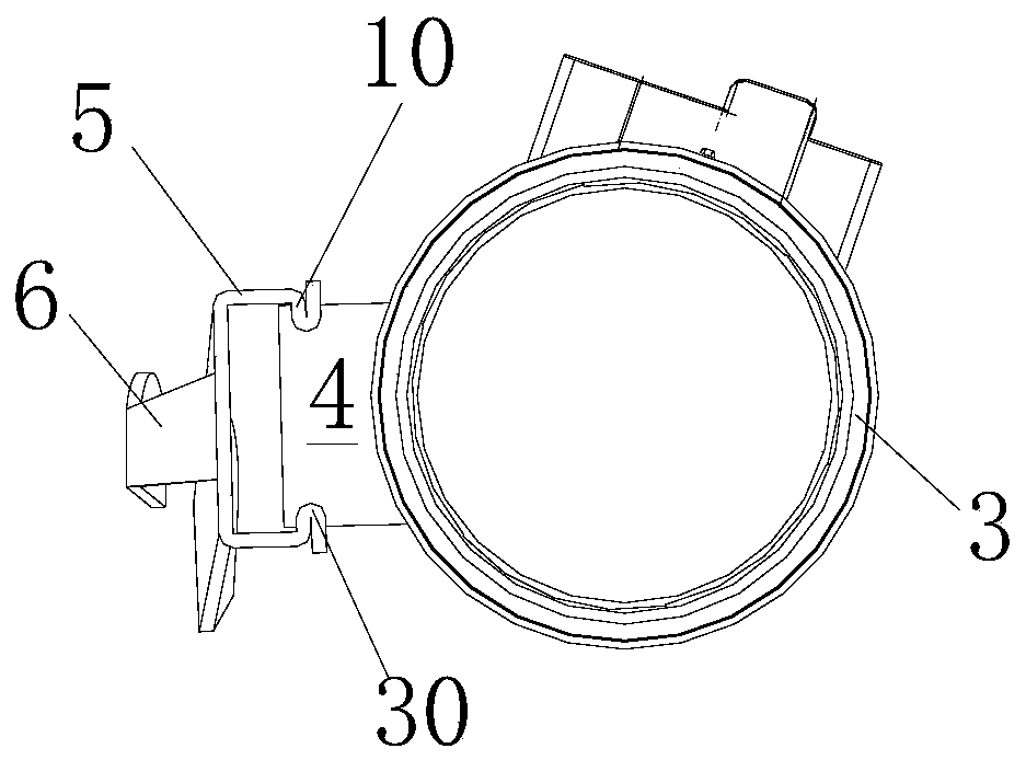
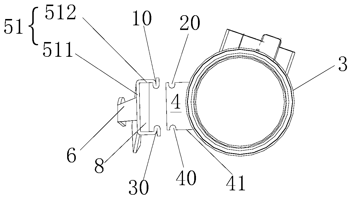
[0028] Such as Figure 1 to Figure 3 As shown, the present disclosure provides an engine intake pipe assembly, including a first hose section 1 with one end for connecting to an engine throttle, a second hose section 2 for connecting to an intercooler at one end, and a second hose section 2 connected to the first A hard pipe section 3 between a hose section 1 and a second hose section 2 and used to be fixed on the vehicle frame, wherein the engine air collecting pipe assembly also includes a first slide rail 4 arranged on the hard pipe section 3, and the hard pipe section 3 The pipe section 3 is slidably connected to the vehicle frame along the axial directi...
PUM
 Abstract
Description
Claims
Application Information
 - R&D
- Intellectual Property
- Life Sciences
- Materials
- Tech Scout
- Unparalleled Data Quality
- Higher Quality Content
- 60% Fewer Hallucinations
Browse by: Latest US Patents, China's latest patents, Technical Efficacy Thesaurus, Application Domain, Technology Topic, Popular Technical Reports.
© 2025 PatSnap. All rights reserved.Legal|Privacy policy|Modern Slavery Act Transparency Statement|Sitemap|About US| Contact US: help@patsnap.com


