A new type of multi-channel central rotary joint for shield machine

A technology of central rotary joints and rotary joints, which is applied in the direction of pipes/pipe joints/fittings, tunnels, adjustable connections, etc., can solve problems such as poor stress conditions, short total length of central rotary joints, long installation cantilever, etc., to achieve The effect of short cantilever length, improved reliability and improved stress conditions

Active Publication Date: 2017-09-12
CHINA RAILWAY ENGINEERING EQUIPMENT GROUP CO LTD
View PDF6 Cites 0 Cited by
  • Summary
  • Abstract
  • Description
  • Claims
  • Application Information

AI Technical Summary

Problems solved by technology

[0004] In order to solve the above-mentioned technical problems, the present invention provides a new type of multi-channel central rotary joint of shield machine, which adopts the hollow shaft rotor and double-layer stator structure to realize the input of multiple channels of improved medium, and the total length of the central rotary joint is relatively short, which solves many problems. The installation cantilever of the road swivel joint is long, and the stress conditions are not good, which improves the overall performance of the center swivel joint and saves space in the length direction

Method used


Image

  • A new type of multi-channel central rotary joint for shield machine
  • A new type of multi-channel central rotary joint for shield machine
  • A new type of multi-channel central rotary joint for shield machine

Examples


Embodiment Construction

[0021] The following will clearly and completely describe the technical solutions in the embodiments of the present invention with reference to the accompanying drawings in the embodiments of the present invention. Obviously, the described embodiments are only some, not all, embodiments of the present invention. Based on the embodiments of the present invention, all other embodiments obtained by persons of ordinary skill in the art without making creative efforts belong to the protection scope of the present invention.

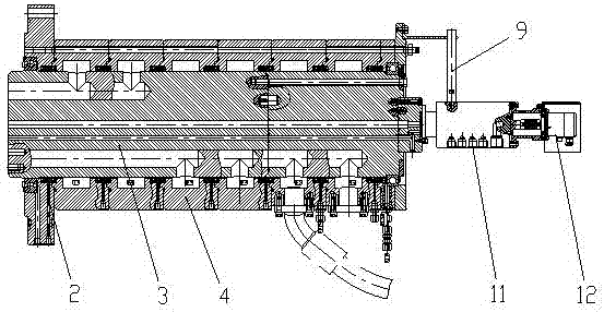
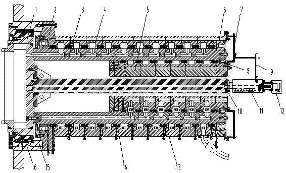
[0022] A new type of multi-channel central rotary joint of shield machine, such as figure 2 As shown, it includes transition piece 1, connecting flange 2, rotor 3, outer ring stator 4, inner ring stator 5, outer ring bearing 6, limit plate 7, inner ring bearing 8, limit rod 9, center transition shaft 10 , the hydraulic rotary joint 11 and the encoder 12, the transition piece 1 is connected with the rotor 3, the connecting flange 2 is connected with the main d...


PUM


Abstract

The invention discloses a novel multi-channel central rotary connector of a shield tunneling machine. The novel multi-channel central rotary connector is characterized in that a connecting flange is connected with a main driving box, a rotor is connected with a transition component and is of a hollow annular structure, an outer ring of the stator is provided with outer-ring stators, and an inner ring of the rotor is provided with inner-ring stators; circular grooves are formed in the outer-ring stators and the inner-ring stators, medium channels are arranged on the rotor, and the circular grooves are communicated with the medium channels; a hydraulic rotary connector is connected with a central transition rotary shaft, and the central transition rotary shaft is connected with the transition component; a rotary encoder is arranged at the rear of the hydraulic rotary connector. The novel multi-channel central rotary connector has the advantages that the novel multi-channel central rotary connector is provided with the rotor with a hollow shaft and double-layer stator structures, improved media can be delivered into the rotor by the inner-ring stators and the outer-ring stators and can be delivered in the multiple channels, the total length of the central rotary connector can be greatly reduced, the central rotary connector is light relatively, a cantilever is short when the novel multi-channel central rotary connector is mounted on the shield tunneling machine, stress conditions can be greatly improved, and the service reliability of the central rotary connector can be improved.

Description

technical field [0001] The invention relates to the technical field of shield tunnel construction equipment, in particular to a novel multi-channel central rotary joint of a shield machine. Background technique [0002] With the rapid development of urban construction, especially the continuous improvement of mechanized construction, the shield method is more and more applied to the construction of railway and highway tunnels. In order to improve the muck excavated by the shield machine, additives such as foam and bentonite need to be passed to the face of the front end of the cutter head through the central rotary joint during the shield construction process. The excavation section of railway and highway tunnels is relatively large, and the excavation diameter is usually about 8-15m. The large-diameter shield machine used in construction requires a large amount of improvement medium for muck improvement, and a multi-channel central rotary joint is required to provide improv...

Claims


Application Information

Patent Timeline
Patent Type & Authority Patents(China)
IPC IPC(8): F16L39/06F16L27/087E21D9/06
CPCE21D9/06F16L27/0849F16L27/087F16L39/06
Inventor 程永龙袁文征常巍峰王杜娟叶蕾
Owner CHINA RAILWAY ENGINEERING EQUIPMENT GROUP CO LTD
Why Eureka
Try Eureka