A beam line deflection magnet assembly, installation method, and rotating frame of the assembly

A deflecting magnet and rotating gantry technology, applied in the directions of X-ray/γ-ray/particle irradiation therapy, radiotherapy, irradiation device, etc., can solve the problem that the total length of the deflecting magnet assembly cannot be reduced, the weight of the rotating gantry is too heavy, and it is inconvenient Medical diagnosis and other issues, to achieve the effect of highlighting the substantive characteristics, reducing the total weight, and shortening the length and space

Active Publication Date: 2021-03-26
CHINA INSTITUTE OF ATOMIC ENERGY
View PDF4 Cites 0 Cited by
  • Summary
  • Abstract
  • Description
  • Claims
  • Application Information

AI Technical Summary

Problems solved by technology

[0009] In view of the problems in the prior art, the present invention proposes a beam line deflection magnet assembly, an installation method, and a rotating frame of the assembly, the purpose of which is to solve the problem that the total length of the existing deflection magnet assembly cannot be reduced, resulting in the overall weight of the rotating frame Problems that are too heavy to rotate and difficult to diagnose medically

Method used


Image

  • A beam line deflection magnet assembly, installation method, and rotating frame of the assembly
  • A beam line deflection magnet assembly, installation method, and rotating frame of the assembly
  • A beam line deflection magnet assembly, installation method, and rotating frame of the assembly

Examples


Embodiment Construction

[0048] Describe in detail below in conjunction with accompanying drawing

[0049] Design principle of the present invention

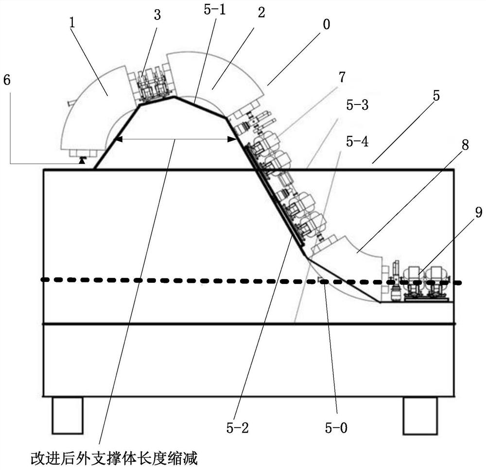
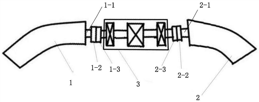
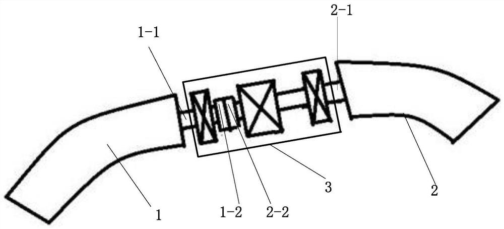
[0050] 1. Advantages and disadvantages of internal mounting flanges. In this embodiment, the flange assembly is arranged inside multiple four-stage lens assemblies. The advantage is that the flange assembly only occupies the minimum gap space between the original coil and the coil. This minimum gap is to ensure that the coil does not collide with the coil. The minimum gap, the minimum gap is only 24 mm, the gap of 24 mm can only accommodate the width of the two flange end caps, if the two flange end caps are connected together, there must be enough space at both ends of the flange end caps for installation The fastening device that connects two flange end caps, for example, in the prior art, an installation space of 100 mm is left for each set of flanges to connect the two flanges. Obviously, when the flange components are arranged on multiple quadrupl...


PUM


Abstract

The invention discloses a beam streamline deflection magnet assembly of a rotating frame. Flanges of the assembly are arranged inside a plurality of four-stage lens assemblies; and the deflection magnet assembly is arranged on an outer support body of the rotating frame at a certain inclination angle and is provided with a positioning base plate. The invention also discloses an installation methodof the deflection magnet assembly. The installation method comprises the following steps: the base plate is placed on an outer support plate of the rotating frame; concentric alignment of the plurality of four-stage lens and a vacuum pipeline is completed; the base plate is drawn out from the lower half part of the plurality of four-stage lens assemblies and then a flange 1 is connected with a flange 2; the lower half part of the plurality of the plurality of four-stage lens assemblies is lifted and restored to a height position before connecting the flanges; and the base plate of the plurality of the four-stage lens assemblies are inserted into the lower part of the plurality of four-stage lens assemblies. The invention also discloses a rotating machine frame for the deflection magnet, wherein the length of the outer support of the machine frame is matched with the length of the deflection magnet, and the deflection magnet is arranged with an inclination angle of 15 degrees to the machine frame. According to the invention, the weight of the external support of the rotating machine frame is reduced by one fifth.

Description

technical field [0001] The invention belongs to the technical field of proton therapy, and in particular relates to a beam line deflection magnet assembly, an installation method, and a rotating frame of the assembly. Background technique [0002] Proton therapy is a type of radiation therapy. After the protons enter the human body, a sharp dose peak is formed at the end of the range, called the Bragg peak. Broadening the Bragg peak by modulating the energy can make the Bragg peak cover the tumor. [0003] Such as figure 1 As shown, the rotating gantry is an important part of the proton therapy equipment. The rotating frame shell includes a cylindrical shell trunk with both ends penetrating and lying horizontally, an outer support body protruding from the upper surface of the cylindrical shell trunk, and an inner support body concave inside the shell. The beam current drawn from the accelerator passes through the transmission of the beam line, enters the rotating frame, ...

Claims


Application Information

Patent Timeline
Patent Type & Authority Patents(China)
IPC IPC(8): A61N5/10G21K5/00G21K5/08
CPCA61N5/10A61N5/1081G21K5/00G21K5/08
Inventor 尹蒙
Owner CHINA INSTITUTE OF ATOMIC ENERGY
Why Eureka
Try Eureka