Projection system and correction method of projection image

A projection system and correction method technology, applied in the field of projection systems, can solve the problems of inconvenient, time-consuming and laborious maintenance of the projection system, and achieve the effect of good correction convenience

Active Publication Date: 2017-10-10
CORETRONIC
View PDF6 Cites 13 Cited by
  • Summary
  • Abstract
  • Description
  • Claims
  • Application Information

AI Technical Summary

Problems solved by technology

In addition, the projection system needs to be calibrated no matter it is used for a long time or the machine is repaired and reassembled, and each calibration needs to be carried out in such a time-consuming and laborious manner, which makes the maintenance of the projection system inconvenient

Method used


Image

  • Projection system and correction method of projection image
  • Projection system and correction method of projection image
  • Projection system and correction method of projection image

Examples


Embodiment Construction

[0025] The foregoing and other technical contents, features and effects of the present invention will be clearly presented in the following detailed description of a preferred embodiment with reference to the accompanying drawings. The directional terms mentioned in the following embodiments, such as: up, down, left, right, front or back, etc., are only referring to the directions of the drawings. Accordingly, the directional terms are used to illustrate and not to limit the invention.

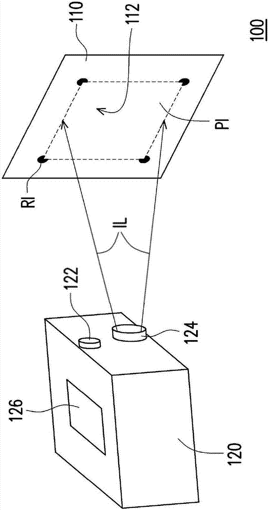
[0026] figure 1 It is a three-dimensional schematic diagram of a projection system according to an embodiment of the present invention. In this embodiment, the projection system 100 includes a projection target 110 and a projection device 120 . The projection device 120 is suitable for projecting the image light beam IL onto the projection target 110 , and the projection target 110 is suitable for receiving the image light beam IL to display the projection picture PI in conjunction with the ...


PUM


Abstract

The invention discloses a projection system and a correction method of a projection image. The projection system comprises a projection target and a projection device. The projection target comprises a reference pattern and receives an image beam to match the image beam to display the projection image. The projection device projects the image beam to the projection target. An image capture device captures a capture image having the projection image and outputs the capture image to the projection device. The projection device adjusts the projection parameters of the image beam according to the projection image in the capture image. Based on the adjusted projection parameters, the image beam displays the reference pattern corresponding to the corrected projection image. By adoption of the correction method of the projection image and the projection system, the projection image of the projection system can be located on a correct position corresponding to the projection target, and thus the automatic correction of the projection image is realized.

Description

technical field [0001] The present invention relates to a projection system, and in particular to a projection system and a method for correcting projection images. Background technique [0002] At present, optical axis correction is a very important part of projection system assembly, especially for embedded projection modules, the relative position of the projector and the projection surface must be adjusted during assembly, so that the projector The projected picture can be presented at the correct position on the projection surface. However, the process of optical axis calibration is time-consuming and labor-intensive, and professionals must use adjustment tools to adjust the projection systems one by one. In addition, if the projection system needs to be assembled separately after leaving the factory, the projection system must be fine-tuned after leaving the factory. If the projector is delivered to the customer in the form of modules, the projection system must be f...

Claims


Application Information

Patent Timeline
Patent Type & Authority Applications(China)
IPC IPC(8): G03B21/14H04N9/31
CPCG03B21/142H04N9/3152H04N9/3185H04N9/3194G06V20/64G06V10/993G06V10/243G06V10/247G06T7/74G06T2207/10024
Inventor 赖桂钦陈治宸
Owner CORETRONIC
Why Eureka
Try Eureka