Transparent object 3D surface reconstruction method and apparatus based on background schlieren technology

A technology for three-dimensional surfaces and transparent objects, applied in 3D modeling, image data processing, instruments, etc., can solve problems such as low spatial resolution and difficult measurement of objects to be measured, and achieve high spatial resolution, convenient measurement, and simple configuration Effect

Active Publication Date: 2017-10-10
NAT UNIV OF DEFENSE TECH
6 Cites 11 Cited by

AI-Extracted Technical Summary

Problems solved by technology

[0004] The present invention provides a method and device for three-dimensional surface reconstruction of transparent objects based on background schlieren technology to solve the ...

Method used

The three-dimensional surface reconstruction device for transparent objects based on background schlieren technology provided in this embodiment obtains light rays when there is a refractive index field by connecting actual object points and actual moving object points; and connecting virtual object points and virtual moving object points Obtaining the light rays when there is no refractive index field; intersecting the light rays when there is a refractive index field and the light rays when there is no refractive index field to form an intersection point, wherein the formed intersection point constitutes the refraction point of the refractive index field; according to the obtained The relative offset between the actual object point and the virtual object point, the relative offset between the actual moving object point and the virtual moving object point, and the refraction point of the refractive index field determine the angular value of the spatial deflection angle. In this embodiment, the space is determined by the obtained relative offset between the actual object point and the virtual object point, the relative offset between the actual moving object point and the virtual moving object point, and the refraction point of the refractive index field. The angle value of the deflection angle is simple and convenient to obtain.
The three-dimensional surface reconstruction device for transparent objects based on background schlieren technology provided in this embodiment obtains the correspondence between the image point and the object point when there is no refractive index field, and the image point and the presence of the refractive index field According to the corresponding relationship between the obtained image point and the object point when there is no refractive index field and the relationship between the image point and the object point when there is a refractive index field The corresponding relationship between them determines the angle value of the space deflection angle. In this embodiment, a single camera can be used to complete the corresponding operation, and the cost is low; the spatial deflection angle is obtained through the relationship between the object point corresponding to the image point with the refractive index field and the object point without the refractive index field , and measure the size of the deflection angle of space, the acquisition method is simple and convenient.
The three-dimensional surface reconstruction device for transparent objects based on the background schlieren technology provided in this embodiment adopts a collimating lens and a camera, and the configuration is simple; based on the background schlieren technology, by obtaining the spatial coordinates and refraction points of the refraction point of the The normal vector of the tangent plane at the point is used to reconstruct the three-dimensional surface of the refractive index field, and the spatial resolution of the measurement is high; the background image is used as the transparent object to be measured, which is convenient for measurement; the corresponding operation can be completed with a single camera, and the cost is low.
The three-dimensional surface reconstruction method of a transparent object based on the background schlieren technique provided in this embodiment, by finding the object point corresponding to the image point and when there is no refractive index field and the object point corresponding to the image point and having refraction The object point in the rate field; obtain the relative offset between the object point corresponding to the image point and the object point in the absence of the refractive index field and the object point corresponding to the image point in the presence of the refractive index field; keep the image The position of the point remains unchanged, and the background image is moved by a set distance along the main optical axis of the collimator lens, and the object point and the moving background image corresponding to the image point and without the refractive index field after the moving background image are found After obtaining the object point corresponding to the image point and when there is a refractive index field; after obtaining the moving background image, the object point corresponding to the image point and when there is no refractive index field and the object point corresponding to the image point after moving the background image The relative offset between object points corresponding to and in the presence of a refractive index field. In this embodiment, by moving the background image by a set distance along the main optical axis direction of the collimator lens, the object point and the moving background corresponding to the image point after the moving background image and when there is no refractive index field are found The object point corresponding to the image point behind the image and when there is a refractive index field, so as to determine the size of the spatial deflection angle, the acquisition method is simple and convenient.
The three-d...

Abstract

The invention discloses a transparent object 3D surface reconstruction method and apparatus based on background schlieren technology. The method includes the following steps: acquiring the angle value of the spatial bending angle which is formed by the light ray which is emitted by a light source and is further transmitted through a background image in the presence of a refractive index field and the light ray which is emitted by a light source and is further transmitted through a background image in the absence of a refractive index field; based on the acquired angle value of the spatial bending angle, obtaining a direction vector of the light ray which irradiates from the background image to a refraction point; based on the obtained direction vector which irradiates from the background image to the refraction point, determining the spatial coordinate of the refraction point and a normal vector in a tangent plane at the refraction point; based on the determined spatial coordinate of the refraction point and the normal vector in a tangent plane at the refraction point, reconstructing a 3D surface of the refractive index field. According to the invention, the method and the apparatus herein have the characteristics of simple configuration, high measured spatial resolution and low cost.

Application Domain

Technology Topic

Image

  • Transparent object 3D surface reconstruction method and apparatus based on background schlieren technology
  • Transparent object 3D surface reconstruction method and apparatus based on background schlieren technology
  • Transparent object 3D surface reconstruction method and apparatus based on background schlieren technology

Examples

  • Experimental program(1)

Example Embodiment

[0063] It should be noted that, in the case of no conflict, the embodiments in the present application and the features in the embodiments can be combined with each other. The present invention will be described in detail below with reference to the accompanying drawings and examples.
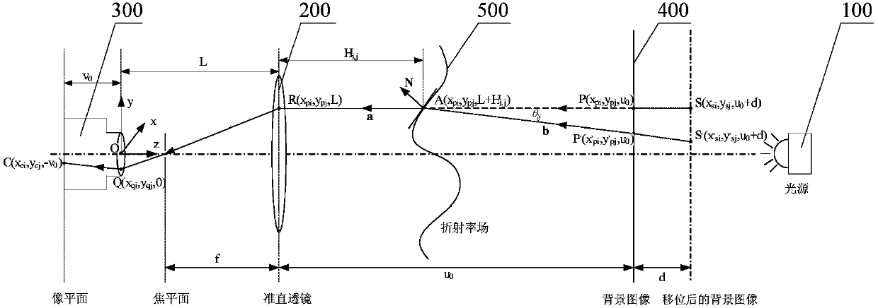
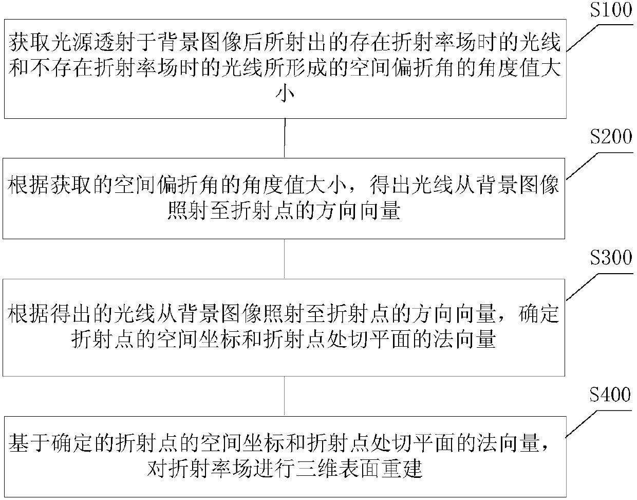
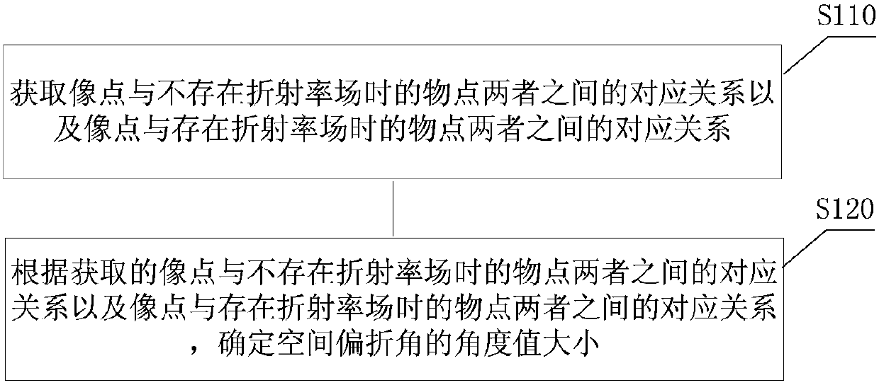
[0064] refer to figure 1 and figure 2 , a preferred embodiment of the present invention provides a three-dimensional surface reconstruction method for transparent objects based on background schlieren technology, which is applied to a three-dimensional surface reconstruction system for a refractive index field. The three-dimensional surface reconstruction system for a refractive index field includes sequentially installed light sources 100, quasi- A straight lens 200 and a camera 300, the light source 100 is used to emit light and transmit the emitted light on the object point of the background image 400; the collimator lens 200 is used to collect the light after passing through the object point and the refraction point of the refractive index field 500 The camera 300 is used to form an image point on the light collected by the collimating lens 200; the three-dimensional surface reconstruction method of a transparent object based on the background schlieren technique includes steps:
[0065] Step S100 , acquiring the angular value of the spatial deflection angle formed by the light rays emitted by the light source when there is a refractive index field and the light rays when there is no refractive index field after the light source is transmitted through the background image.
[0066] like figure 1 As shown, the diaphragm is placed at the focal point of the collimator lens 200 to ensure that only light rays parallel to the optical axis can pass through the diaphragm. When the light source 100 is transmitted through the background image 400, assuming that there is no refractive index field 500, point P is a virtual object point in the background lattice corresponding to the image point C captured by the camera 300 when there is no refractive index field. Assuming that the refractive index field 500 exists, when the refractive index field is introduced, the actual object point corresponding to the image point C moves to the point P' due to the influence of the refractive index field. please see figure 1 , Point A represents the refraction point of light in the refractive index field, point Q represents the incident point of light on the equivalent camera lens, and point R represents the incident point of light on the collimator lens. By obtaining the offset between the virtual object point P when there is no refractive index field and the actual object point P' when there is a refractive index field, draw the ray when there is a refractive index field and the ray when there is no refractive index field ; Among them, the spatial deflection angle formed between the light when there is a refractive index field and the light when there is no refractive index field is θ i,j , θ i,j The size of the angle value can be obtained through actual measurement.
[0067] Step S200 , according to the obtained angular value of the spatial deflection angle, obtain the direction vector of the light irradiating from the background image to the refraction point.
[0068] According to the measured spatial deflection angle θ i,j The magnitude of the angle value and the offset between the virtual object point P when there is no refractive index field and the actual object point P' when there is a refractive index field, calculate the direction vector of the light from the background image to the refraction point A
[0069] Step S300, according to the obtained direction vector of light irradiating from the background image to the refraction point, determine the space coordinates of the refraction point and the normal vector of the tangent plane at the refraction point.
[0070] According to the calculated direction vector of light from the background image to the refraction point A Obtain the Z-axis physical coordinate H corresponding to the refraction point A (interrogation area grid node i, j) ij, , based on the one-to-one correspondence between grid nodes and physical coordinates in the interrogation area, determine the spatial coordinates of refraction point A (x pi ,y pj ,L+H i,j ). And according to the space form of Snell (Snell) law, calculate the normal vector of the tangent plane at the refraction point
[0071] Step S400, perform three-dimensional surface reconstruction on the refractive index field based on the determined spatial coordinates of the refraction point and the normal vector of the tangent plane at the refraction point.
[0072] Based on the acquired spatial coordinates of refraction point A (x pi ,y pj ,L+H i,j ) and the normal vector of the tangent plane at the refraction point The Gaussian Kernel (Gaussian kernel function) method is used to realize the three-dimensional surface reconstruction of the refractive index field. In this embodiment, the three-dimensional surface of the refractive index field is reconstructed by sequentially obtaining the space coordinates of each refraction point of the refraction index field and the normal vector of the tangent plane at the refraction point.
[0073] The three-dimensional surface reconstruction method of transparent objects based on the background schlieren technology provided in this embodiment adopts a collimator lens and a camera, and the configuration is simple; The normal vector of the plane is used to reconstruct the three-dimensional surface of the refractive index field, and the spatial resolution of the measurement is high; the background image is used as the transparent object to be measured, which is convenient for measurement; the corresponding operation can be completed with a single camera, and the cost is low.
[0074] Preferably, as image 3 As shown, in the method for reconstructing the three-dimensional surface of a transparent object based on the background schlieren technique provided in this embodiment, step S100 includes:
[0075] Step S110, obtaining the correspondence between the image point and the object point when there is no refractive index field, and the correspondence between the image point and the object point when there is a refractive index field.
[0076] Obtain the correspondence between the image point C and the object point P when there is no refractive index field and the correspondence between the image point C and the object point P' when there is a refractive index field, for example, using a camera to capture The physical coordinate positions of the object point P corresponding to the image point C when there is no refractive index field and the object point P' corresponding to the image point C when there is a refractive index field.
[0077] Step S120, according to the corresponding relationship between the acquired image point and the object point when there is no refractive index field and the corresponding relationship between the image point and the object point when there is a refractive index field, determine the spatial deflection angle Angle value size.
[0078] According to the corresponding relationship between the obtained image point C and the object point P when there is no refractive index field and the corresponding relationship between the image point C and the object point P' when there is a refractive index field, the existence of refraction is obtained The light in the rate field and the light in the absence of the refractive index field, and the spatial deflection angle θ formed by the light in the presence of the refractive index field and the light in the absence of the refractive index field i,j , and determine the spatial deflection angle θ by measuring i,j The size of the angle value.
[0079] The 3D surface reconstruction method of a transparent object based on the background schlieren technology provided in this embodiment obtains the correspondence between the image point and the object point when there is no refractive index field, and the image point and the object point when there is a refractive index field. The corresponding relationship between the two points, and according to the corresponding relationship between the acquired image point and the object point when there is no refractive index field and the correspondence between the image point and the object point when there is a refractive index field Relationship, to determine the angle value of the space deflection angle. In this embodiment, a single camera can be used to complete the corresponding operation, and the cost is low; the spatial deflection angle is obtained through the relationship between the object point corresponding to the image point with the refractive index field and the object point without the refractive index field , and measure the size of the deflection angle of space, the acquisition method is simple and convenient.
[0080] Further, as Figure 4 As shown, in the method for reconstructing the three-dimensional surface of a transparent object based on the background schlieren technique provided in this embodiment, step S110 includes:
[0081]Step S111, find out the object point corresponding to the image point when there is no refractive index field and the object point corresponding to the image point when there is a refractive index field, wherein the object point corresponding to the image point and there is no refractive index field The object point in the refractive index field is called the virtual object point, and the object point corresponding to the image point and in the presence of the refractive index field is called the actual object point.
[0082] Use the camera to capture the object point P corresponding to the image point C when there is no refractive index field and the object point P' corresponding to the image point C when there is a refractive index field. The corresponding object point P when there is no refractive index field is defined as a virtual object point. The object point P' corresponding to the image point C and in the presence of the refractive index field is defined as the actual object point.
[0083] Step S112, obtaining the relative offset between the actual object point and the virtual object point.
[0084] Obtain the physical coordinate positions of the actual object point P' and the virtual object point P, and obtain the relative offset between the actual object point P' and the virtual object point P (Δx pi ,Δy pj ).
[0085] Step S113, keeping the position of the image point unchanged, moving the background image by a set distance along the main optical axis direction of the collimating lens, and finding the object corresponding to the image point after moving the background image and having no refractive index field point and the object point corresponding to the image point after moving the background image and when there is a refractive index field, among them, the object point corresponding to the image point after moving the background image and when there is no refractive index field is called virtual movement Object point, the object point corresponding to the image point after moving the background image and the object point when there is a refractive index field is called the actual moving object point.
[0086] In the case of keeping the position of each component and image point C in the three-dimensional surface reconstruction system of the refractive index field unchanged, move the background image along the main optical axis direction of the collimating lens by a set distance d. The moving distance d should be within the depth of field of the camera In order to be careful not to defocus too much, please see figure 1 , after the background image moves a set distance d along the main optical axis of the collimator lens, the object point corresponding to image point C and without the refractive index field becomes S; the object point corresponding to image point C and with the existence of the refractive index field In this embodiment, the object point S after moving the background image corresponding to the image point and when there is no refractive index field is defined as a virtual moving object point. The object point S′ corresponding to the image point after moving the background image and when there is a refractive index field is defined as the actual moving object point.
[0087] Step S114, acquiring the relative offset between the actual moving object point and the virtual moving object point.
[0088] Obtain the physical coordinate positions of the actual moving object point S' and the virtual moving object point S, and obtain the relative offset between the actual moving object point S' and the virtual moving object point S based on the BOS method (Δx si ,Δy sj ).
[0089] The 3D surface reconstruction method of a transparent object based on the background schlieren technique provided in this embodiment, finds out the object point corresponding to the image point when there is no refractive index field and the object point corresponding to the image point when there is a refractive index field the object point; obtain the relative offset between the object point corresponding to the image point and when there is no refractive index field and the object point corresponding to the image point and exist when the refractive index field exists; keep the position of the image point remains unchanged, move the background image along the main optical axis direction of the collimating lens for a set distance, find out the object point corresponding to the image point after moving the background image and when there is no refractive index field and the object point after moving the background image and The object point corresponding to the image point and when there is a refractive index field; the object point corresponding to the image point after obtaining the moving background image and when there is no refractive index field and the object point corresponding to the image point after moving the background image and The relative offset between object points in the presence of a refractive index field. In this embodiment, by moving the background image by a set distance along the main optical axis direction of the collimator lens, the object point and the moving background corresponding to the image point after the moving background image and when there is no refractive index field are found The object point corresponding to the image point behind the image and when there is a refractive index field, so as to determine the size of the spatial deflection angle, the acquisition method is simple and convenient.
[0090] Optionally, as in Figure 5 As shown, in the method for reconstructing the three-dimensional surface of a transparent object based on background schlieren technology provided in this embodiment, step S120 includes:
[0091] Step S121 , connecting the actual object point and the actual moving object point to obtain the ray when the refractive index field exists; and connecting the virtual object point and the virtual moving object point to obtain the ray without the refractive index field.
[0092] In this embodiment, the actual object point P' and the actual moving object point S' are connected by a straight line to obtain light rays when there is a refractive index field. The virtual object point P and the virtual moving object point S are connected together by a straight line to obtain light rays when there is a refractive index field.
[0093] Step S122. Intersect the light rays when there is a refractive index field and the light rays when there is no refractive index field to form an intersection point, wherein the formed intersection point constitutes a refraction point of the refractive index field;
[0094] please see figure 1 , the light rays when there is a refractive index field and the light rays when there is no refractive index field are intersected, and the intersection point A is formed at the intersection of the two rays, and the intersection point A formed here is the refraction point of the refractive index field.
[0095] Step S123, according to the acquired relative offset between the actual object point and the virtual object point, the relative offset between the actual moving object point and the virtual moving object point, and the refraction point of the refractive index field, determine the spatial deflection angle Angle value size.
[0096] According to the relative offset between the obtained actual object point and the virtual object point (Δx pi ,Δy pj ), the relative offset between the actual moving object point and the virtual moving object point (Δx si ,Δy sj ) and the refraction point A of the refractive index field, through the actual measurement, determine the spatial deflection angle θ i,j The size of the angle value.
[0097] The method for reconstructing the three-dimensional surface of a transparent object based on the background schlieren technology provided in this embodiment obtains the light rays when there is a refractive index field by connecting the actual object point and the actual moving object point; and connects the virtual object point and the virtual moving object point to obtain The light in the refractive index field; the light in the presence of the refractive index field and the light in the absence of the refractive index field are intersected to form an intersection point, wherein the formed intersection point constitutes the refraction point of the refractive index field; according to the obtained actual object The relative offset between the point and the virtual object point, the relative offset between the actual moving object point and the virtual moving object point, and the refraction point of the refractive index field determine the angular value of the spatial deflection angle. In this embodiment, the space is determined by the obtained relative offset between the actual object point and the virtual object point, the relative offset between the actual moving object point and the virtual moving object point, and the refraction point of the refractive index field. The angle value of the deflection angle is simple and convenient to obtain.
[0098] Preferably, as Image 6 As shown, in the method for reconstructing the three-dimensional surface of a transparent object based on the background schlieren technique provided in this embodiment, step S300 includes:
[0099] Step S310, acquiring the physical coordinates of the refraction point, and determining the spatial coordinates of the refraction point according to the physical coordinates of the refraction point and the corresponding relationship between the physical coordinates and the spatial coordinates.
[0100] According to the determined space deflection angle θ i,j Calculate the physical coordinates of the refraction point A, where the Z-axis physical coordinates H of the refraction point A ij for:
[0101] ||P'-P||=(u 0 -H i,j )tanθ i,j (1)
[0102] in, Indicates the distance between the actual object point P' and the virtual object point P; u0 indicates the distance from the background image to the collimator lens; θ i,j is the deflection angle of space.
[0103] Obtain the Z-axis physical coordinate H corresponding to the refraction point A (interrogation area grid node i, j) from formula 1 ij ,, based on the one-to-one correspondence between grid nodes and physical coordinates in the interrogation area, determine the spatial coordinates of refraction point A (x pi ,y pj ,L+H i,j ).
[0104] Step S320 : Calculate the normal vector of the tangent plane at the refraction point according to the acquired direction vector of the light irradiating from the background image to the refraction point and the direction vector of the light from the refraction point to the collimator lens.
[0105] According to the direction vector of light from the background image to the refraction point A and the direction vector of the light from the refraction point A to the collimating lens Based on the spatial form of Snell's law, the normal vector of the tangent plane at the refraction point is calculated
[0106]
[0107] in, is the space direction vector of the light from the refraction point to the collimating lens; is the direction vector of light from the background image to the refraction point A; n represents the refractive index of the refractive index field, and the refractive index of air is approximately 1.
[0108] Since the space direction vector It is a known quantity parallel to the principal optical axis z-axis, so the normal vector of the tangent plane at the refraction point can be determined from formula 2
[0109] The three-dimensional surface reconstruction method of a transparent object based on the background schlieren technology provided in this embodiment, obtains the physical coordinates of the refraction point, and determines the spatial coordinates of the refraction point according to the physical coordinates of the refraction point and the corresponding relationship between the physical coordinates and the spatial coordinates; Obtain the direction vector of the light from the background image to the refraction point and the direction vector of the light from the refraction point to the collimator lens, and calculate the normal vector of the tangent plane at the refraction point. In this embodiment, the spatial coordinates of the refraction point and the normal vector of the tangent plane at the refraction point can be automatically calculated, with a high degree of automation, and the reconstruction speed of the three-dimensional surface of the temperature of the transparent object is fast.
[0110] like figure 1 and Figure 7 As shown, this embodiment also provides a three-dimensional surface reconstruction device for transparent objects based on background schlieren technology. The three-dimensional surface reconstruction system for the refractive index field includes a light source 100, a collimating lens 200, and a camera 300 installed in sequence. The light source 100 is used to emit and transmit the emitted light on the object point of the background image 400; the collimating lens 200 is used to collect the light after passing through the object point and the refraction point of the refractive index field 500; the camera 300 is used to align The light rays form an image point; the three-dimensional surface reconstruction device of a transparent object based on the background schlieren technology includes: an angle acquisition module 10, which is used to acquire the light rays emitted by the light source transmitted through the background image when there is a refractive index field and when there is no refractive index field The angle value of the space deflection angle formed by the light at the time; the vector acquisition module 20 is used to obtain the direction vector of the light from the background image to the refraction point according to the angle value of the acquired space deflection angle; the determination module 30, It is used to determine the spatial coordinates of the refraction point and the normal vector of the tangent plane at the refraction point according to the obtained direction vector of the light irradiated from the background image to the refraction point; the three-dimensional reconstruction module 40 is used to determine the spatial coordinates and The normal vector of the tangent plane at the point of refraction, to perform a 3D surface reconstruction of the refractive index field.
[0111] like figure 1As shown, the diaphragm is placed at the focal point of the collimator lens 200 to ensure that only light rays parallel to the optical axis can pass through the diaphragm. When the light source 100 is transmitted through the background image 400, assuming that there is no refractive index field 500, point P is a virtual object point in the background lattice corresponding to the image point C captured by the camera 300 when there is no refractive index field. Assuming that the refractive index field 500 exists, when the refractive index field is introduced, the actual object point corresponding to the image point C moves to the point P' due to the influence of the refractive index field. please see figure 1 , Point A represents the refraction point of light in the refractive index field, point Q represents the incident point of light on the equivalent camera lens, and point R represents the incident point of light on the collimator lens.
[0112] The angle acquisition module 10 obtains the offset between the virtual object point P when there is no refractive index field and the actual object point P' when there is a refractive index field, and draws the light rays when there is a refractive index field and when there is no refractive index field field; where, the spatial deflection angle formed between the light when there is a refractive index field and the light when there is no refractive index field is θ i,j , θ i,j The size of the angle value can be obtained through actual measurement.
[0113] The vector acquisition module 20 obtains the space deflection angle θ according to the measurement i,j The magnitude of the angle value and the offset between the virtual object point P when there is no refractive index field and the actual object point P' when there is a refractive index field, calculate the direction vector of the light from the background image to the refraction point A
[0114] The determination module 30 is based on the calculated direction vector of light from the background image to the refraction point A Obtain the Z-axis physical coordinate H corresponding to the grid node i and j in the interrogation area of ​​refraction point A ij, , based on the one-to-one correspondence between grid nodes and physical coordinates in the interrogation area, determine the spatial coordinates of refraction point A (x pi ,y pj ,L+H i,j ). And according to the space form of Snell (Snell) law, calculate the normal vector of the tangent plane at the refraction point
[0115] The three-dimensional reconstruction module 40 is based on the acquired spatial coordinates (x pi ,y pj ,L+H i,j ) and the normal vector of the tangent plane at the refraction point The Gaussian Kernel (Gaussian kernel function) method is used to realize the three-dimensional surface reconstruction of the refractive index field. In this embodiment, the three-dimensional surface of the refractive index field is reconstructed by sequentially obtaining the space coordinates of each refraction point of the refraction index field and the normal vector of the tangent plane at the refraction point.
[0116] The three-dimensional surface reconstruction device for transparent objects based on the background schlieren technology provided in this embodiment adopts a collimating lens and a camera, and the configuration is simple; The normal vector of the plane is used to reconstruct the three-dimensional surface of the refractive index field, and the spatial resolution of the measurement is high; the background image is used as the transparent object to be measured, which is convenient for measurement; the corresponding operation can be completed with a single camera, and the cost is low.
[0117] Preferably, as Figure 8 As shown, in the three-dimensional surface reconstruction device for transparent objects based on background schlieren technology provided in this embodiment, the angle acquisition module 10 includes: an object point acquisition unit 11, which is used to acquire both the image point and the object point when there is no refractive index field The corresponding relationship between the image point and the object point when there is a refractive index field; the determination unit 12 is used to obtain the image point and the object point when there is no refractive index field. The corresponding relationship between the image point and the object point when there is a refractive index field determines the angle value of the spatial deflection angle.
[0118] The object point acquisition unit 11 acquires the correspondence between the image point C and the object point P when there is no refractive index field and the correspondence between the image point C and the object point P' when there is a refractive index field, For example, the camera captures the physical coordinate positions of the object point P corresponding to the image point C when there is no refractive index field and the object point P' corresponding to the image point C when there is a refractive index field.
[0119] The determining unit 12 is based on the obtained correspondence between the image point C and the object point P when there is no refractive index field and the correspondence between the image point C and the object point P' when there is a refractive index field, Obtain the light when there is a refractive index field and the light when there is no refractive index field, and obtain the spatial deflection angle θ formed by the light when there is a refractive index field and the light when there is no refractive index field i,j , and determine the spatial deflection angle θ by measuring i,j The size of the angle value.
[0120] The 3D surface reconstruction device for transparent objects based on the background schlieren technology provided in this embodiment obtains the corresponding relationship between the image point and the object point when there is no refractive index field, and the image point and the object point when there is a refractive index field. The corresponding relationship between the two points, and according to the corresponding relationship between the acquired image point and the object point when there is no refractive index field and the correspondence between the image point and the object point when there is a refractive index field Relationship, to determine the angle value of the space deflection angle. In this embodiment, a single camera can be used to complete the corresponding operation, and the cost is low; the spatial deflection angle is obtained through the relationship between the object point corresponding to the image point with the refractive index field and the object point without the refractive index field , and measure the size of the deflection angle of space, the acquisition method is simple and convenient.
[0121] Preferably, as Figure 9 As shown, in the 3D surface reconstruction device for transparent objects based on the background schlieren technology provided in this embodiment, the object point acquisition unit 11 includes: an object point search subunit 111, which is used to find out the corresponding image point without refractive index The object point in the field and the object point corresponding to the image point in the presence of the refractive index field, among them, the object point corresponding to the image point in the absence of the refractive index field is called a virtual object point, and the object point corresponding to the image point The corresponding object point when there is a refractive index field is called the actual object point; the first relative offset acquisition subunit 112 is used to acquire the relative offset between the actual object point and the virtual object point; the mobile search subunit 113. It is used to keep the position of the image point unchanged, move the background image along the direction of the main optical axis of the collimator lens for a set distance, and find out the position corresponding to the image point after moving the background image and when there is no refractive index field The object point and the object point corresponding to the image point after moving the background image and when there is a refractive index field, among them, the object point corresponding to the image point after moving the background image and when there is no refractive index field is called virtual The moving object point, the object point corresponding to the image point after moving the background image and having a refractive index field is called the actual moving object point; the second relative offset acquisition subunit 114 is used to obtain the actual moving object point and The relative offset between virtual moving object points.
[0122] The object point search subunit 111 uses the camera to capture the object point P corresponding to the image point C when there is no refractive index field and the object point P' corresponding to the image point C when there is a refractive index field. In this embodiment , the object point P corresponding to the image point C and when there is no refractive index field is defined as a virtual object point. The object point P' corresponding to the image point C and in the presence of the refractive index field is defined as the actual object point.
[0123] The first relative offset acquisition subunit 112 acquires the physical coordinate positions of the actual object point P' and the virtual object point P, and obtains the actual object point P' and the virtual object point P' based on the BOS (Background Oriented Schlieren, background schlieren mode) method. Relative offset between points P (Δx pi ,Δy pj ).
[0124] The mobile search subunit 113 moves the background image along the main optical axis direction of the collimator lens by a set distance d while keeping the positions of the components and the image point C in the three-dimensional surface reconstruction system of the refractive index field unchanged. Within the depth of field of the camera, take care not to defocus too much, see figure 1 , after the background image moves a set distance d along the main optical axis of the collimator lens, the object point corresponding to image point C and without the refractive index field becomes S; the object point corresponding to image point C and with the existence of the refractive index field In this embodiment, the object point S after moving the background image corresponding to the image point and when there is no refractive index field is defined as a virtual moving object point. The object point S′ corresponding to the image point after moving the background image and when there is a refractive index field is defined as the actual moving object point.
[0125] The second relative offset acquisition subunit 114 acquires the physical coordinate positions of the actual moving object point S' and the virtual moving object point S, and obtains the relative offset between the actual moving object point S' and the virtual moving object point S based on the BOS method Quantity (Δx si ,Δy sj ).
[0126] The 3D surface reconstruction device for transparent objects based on the background schlieren technology provided in this embodiment, finds the object point corresponding to the image point when there is no refractive index field and the object point corresponding to the image point when there is a refractive index field. the object point; obtain the relative offset between the object point corresponding to the image point and when there is no refractive index field and the object point corresponding to the image point and exist when the refractive index field exists; keep the position of the image point remains unchanged, move the background image along the main optical axis direction of the collimating lens for a set distance, find out the object point corresponding to the image point after moving the background image and when there is no refractive index field and the object point after moving the background image and The object point corresponding to the image point and when there is a refractive index field; the object point corresponding to the image point after obtaining the moving background image and when there is no refractive index field and the object point corresponding to the image point after moving the background image and The relative offset between object points in the presence of a refractive index field. In this embodiment, by moving the background image by a set distance along the main optical axis direction of the collimating lens, the object point and the moving background corresponding to the image point after the moving background image and when there is no refractive index field are found The object point corresponding to the image point behind the image and when there is a refractive index field, so as to determine the size of the spatial deflection angle, the acquisition method is simple and convenient.
[0127] Further, as Figure 10 As shown, in the 3D surface reconstruction device for transparent objects based on background schlieren technology provided in this embodiment, the determination unit 12 includes: a connection subunit 121, which is used to connect the actual object point and the actual moving object point to obtain the light rays when there is a refractive index field ; and connect the virtual object point and the virtual moving object point to obtain the light when there is no refractive index field; the intersection subunit 122 is used to merge the light when there is a refractive index field and the light when there is no refractive index field and form an intersection point, wherein the formed intersection point constitutes the refraction point of the refractive index field; the angle value determination subunit 123 is used to obtain the relative offset between the actual object point and the virtual object point, the actual moving object point and the virtual moving The relative offset between object points and the refraction point of the refractive index field determine the angular value of the spatial deflection angle.
[0128] In this embodiment, the connection subunit 121 connects the actual object point P' and the actual moving object point S' together by a straight line, and obtains light rays when there is a refractive index field. The virtual object point P and the virtual moving object point S are connected together by a straight line to obtain light rays when there is a refractive index field.
[0129] please see figure 1 , the intersection subunit 122 merges the light rays when there is a refractive index field and the light rays when there is no refractive index field, and forms an intersection point A at the intersection of the two rays, and the intersection point A formed here is the value of the refractive index field refraction point.
[0130] The angle value determining subunit 123 is based on the acquired relative offset between the actual object point and the virtual object point (Δx pi ,Δy pj ), the relative offset between the actual moving object point and the virtual moving object point (Δx si ,Δy sj ) and the refraction point A of the refractive index field, through the actual measurement, determine the spatial deflection angle θ i,j The size of the angle value.
[0131]The 3D surface reconstruction device for transparent objects based on the background schlieren technology provided in this embodiment obtains light rays when there is a refractive index field by connecting actual object points and actual moving object points; The light in the refractive index field; the light in the presence of the refractive index field and the light in the absence of the refractive index field are intersected to form an intersection point, wherein the formed intersection point constitutes the refraction point of the refractive index field; according to the obtained actual object The relative offset between the point and the virtual object point, the relative offset between the actual moving object point and the virtual moving object point, and the refraction point of the refractive index field determine the angular value of the spatial deflection angle. In this embodiment, the space is determined by the obtained relative offset between the actual object point and the virtual object point, the relative offset between the actual moving object point and the virtual moving object point, and the refraction point of the refractive index field. The angle value of the deflection angle is simple and convenient to obtain.
[0132] Optionally, as in Figure 11 As shown, in the three-dimensional surface reconstruction device for transparent objects based on background schlieren technology provided in this embodiment, the determination module 30 includes: a space coordinate determination unit 31, which is used to obtain the physical coordinates of the refraction points, and according to the physical coordinates of the refraction points and the physical The corresponding relationship between the coordinates and the spatial coordinates determines the spatial coordinates of the refraction point; the calculation unit 32 is used to calculate the direction vector of the acquired light from the background image to the refraction point and the direction vector of the light from the refraction point to the collimating lens. The normal vector of the tangent plane at the refraction point.
[0133] According to the determined space deflection angle θ i,j Calculate the physical coordinates of the refraction point A, where the Z-axis physical coordinates H of the refraction point A ij for:
[0134] ||P'-P||=(u 0 -H i,j )tanθ i,j (3)
[0135] in, Indicates the distance between the actual object point P' and the virtual object point P; u 0 Indicates the distance from the background image to the collimating lens; θ i,j is the deflection angle of space.
[0136] Obtain the Z-axis physical coordinate H corresponding to the refraction point A (interrogation area grid node i, j) from formula 1 ij ,, based on the one-to-one correspondence between grid nodes and physical coordinates in the interrogation area, determine the spatial coordinates of refraction point A (x pi ,y pj ,L+H i,j ).
[0137] According to the direction vector of light from the background image to the refraction point A and the direction vector of the light from the refraction point A to the collimating lens Based on the spatial form of Snell's law, the normal vector of the tangent plane at the refraction point is calculated
[0138]
[0139] in, is the space direction vector of the light from the refraction point to the collimating lens; is the direction vector of light from the background image to the refraction point A; n represents the refractive index of the refractive index field, and the refractive index of air is approximately 1.
[0140] Since the space direction vector It is a known quantity parallel to the principal optical axis z-axis, so the normal vector of the tangent plane at the refraction point can be determined from formula 2
[0141] The three-dimensional surface reconstruction device for transparent objects based on the background schlieren technology provided in this embodiment determines the spatial coordinates of the refraction points according to the physical coordinates of the refraction points and the corresponding relationship between the physical coordinates and the spatial coordinates by obtaining the physical coordinates of the refraction points; Obtain the direction vector of the light from the background image to the refraction point and the direction vector of the light from the refraction point to the collimator lens, and calculate the normal vector of the tangent plane at the refraction point. In this embodiment, the spatial coordinates of the refraction point and the normal vector of the tangent plane at the refraction point can be automatically calculated, with a high degree of automation, and the reconstruction speed of the three-dimensional surface of the temperature of the transparent object is fast.
[0142] The above descriptions are only preferred embodiments of the present invention, and are not intended to limit the present invention. For those skilled in the art, the present invention may have various modifications and changes. Any modifications, equivalent replacements, improvements, etc. made within the spirit and principles of the present invention shall be included within the protection scope of the present invention.

PUM

no PUM

Description & Claims & Application Information

We can also present the details of the Description, Claims and Application information to help users get a comprehensive understanding of the technical details of the patent, such as background art, summary of invention, brief description of drawings, description of embodiments, and other original content. On the other hand, users can also determine the specific scope of protection of the technology through the list of claims; as well as understand the changes in the life cycle of the technology with the presentation of the patent timeline. Login to view more.

Similar technology patents

Endoscope apparatus

Owner:OLYMPUS CORP

Classification and recommendation of technical efficacy words

  • Simple configuration
  • Improve spatial resolution
Why Eureka
Try Eureka