Massage chair

A technology of massage chairs and cushions, which is applied in the directions of roller massage, kneading massage apparatus, massage auxiliary products, etc., can solve the problem of lack of corresponding technical support, etc., and achieve the effect of reliable walking and improved comfort.

Pending Publication Date: 2017-10-13
ZHEJIANG HAOZHONGHAO HEALTH PROD
View PDF1 Cites 11 Cited by
  • Summary
  • Abstract
  • Description
  • Claims
  • Application Information

AI Technical Summary

Problems solved by technology

However, there is no corresponding disclosure on the track carrying the massage movement, how to cooperate with the two racks to eliminate the gap generated during angle adjustment; in addition, in order to maintain the meshing between the gear and the rack, a roller is provided under the gear. The roller hooks the lower edge of the straight rack. When switching between the curved rack and the straight rack, there is no corresponding technical support for how to ensure the smooth transition of the roller while the gear meshes with the rack.

Method used


Image

  • Massage chair
  • Massage chair
  • Massage chair

Examples


Embodiment 1

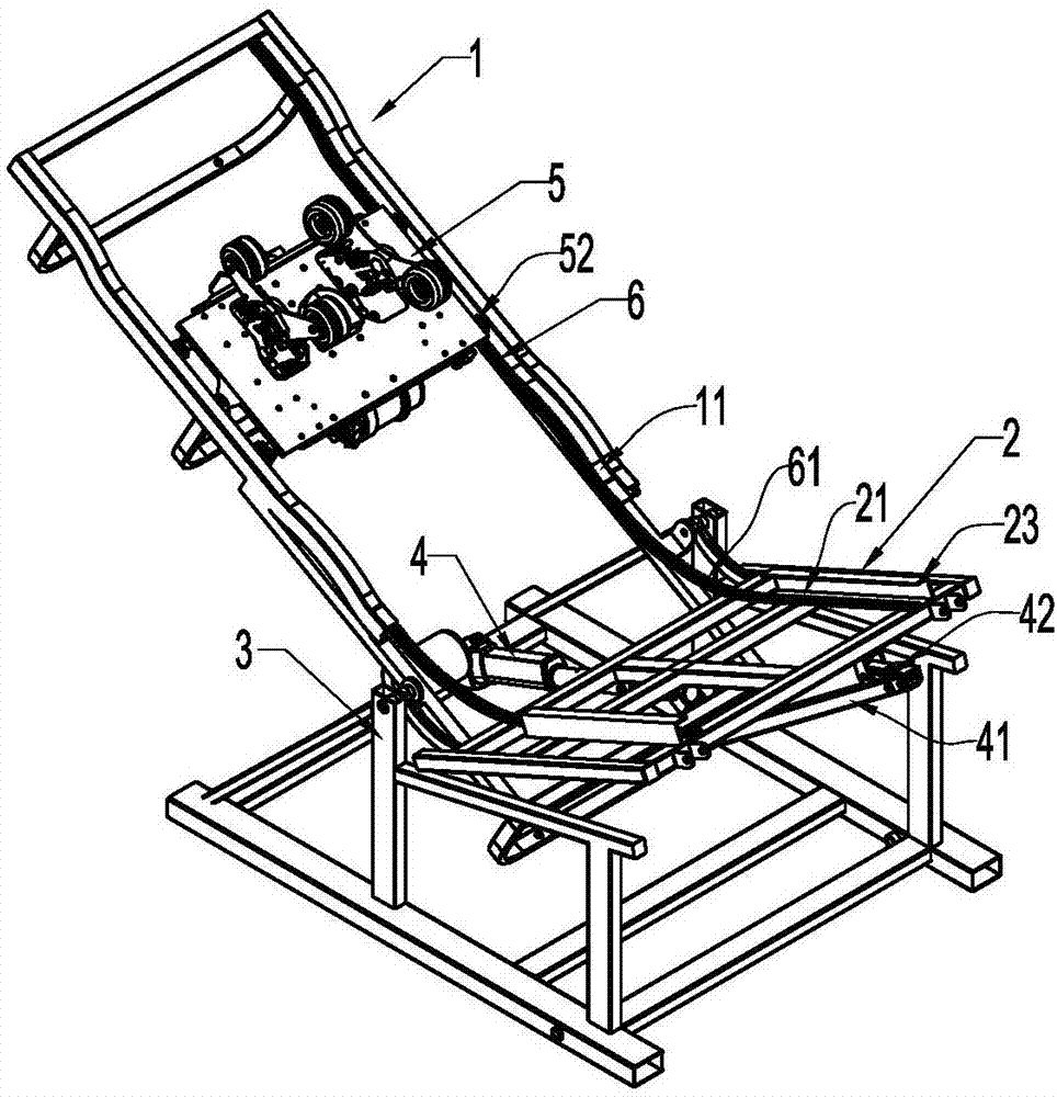
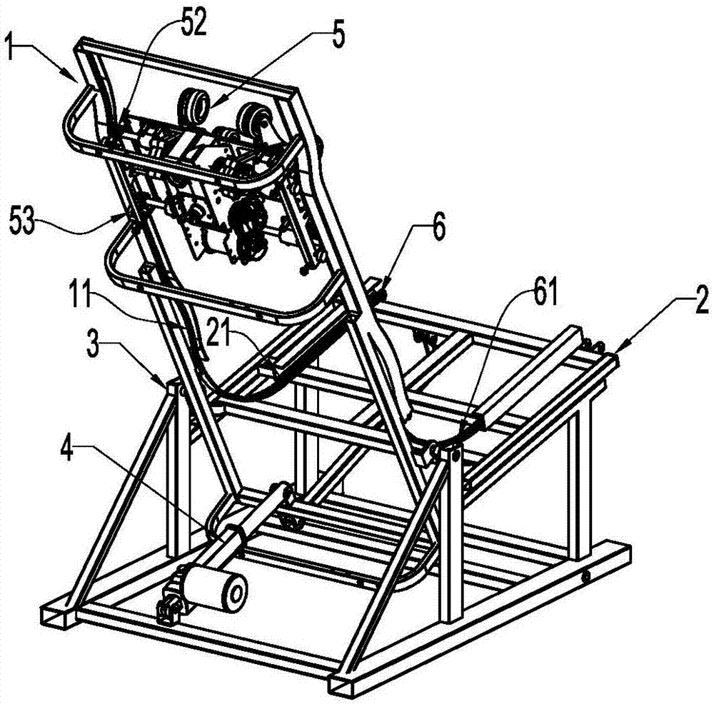
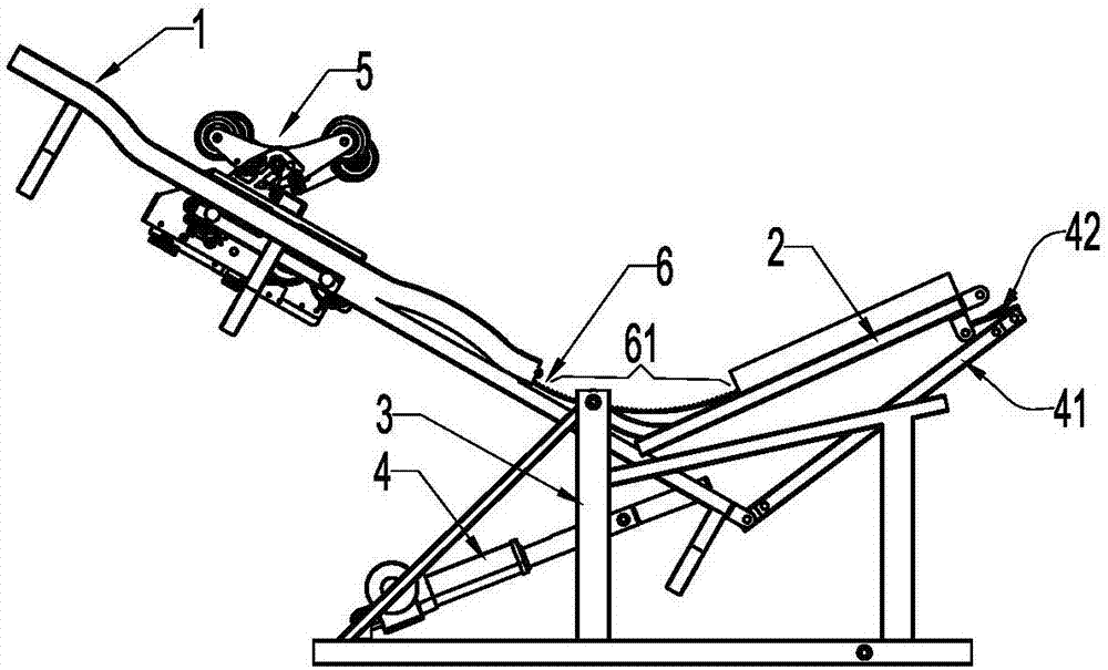
[0039] refer to Figure 1 to Figure 5 , a massage chair, including a backrest frame 1, a cushion frame 2, a seat frame 3, an electric push rod 4 and a massage movement 5; the backrest frame 1 and the cushion frame 2 form a frame structure, and corresponding backrest rail beams 11 are respectively arranged on both sides And cushion rail beam 21; On backrest rail beam 11 and cushion rail beam 21, be fixed with continuous rack 6 or chain, this tooth bar 6 or chain one side are suspended in the air between backrest rail beam 11 and cushion rail beam 21 in this example Inner side, and tooth bar 6 or chain are at backrest rail beam 11 and cushion rail beam 21 close ends, have a suspended section 61, and this suspended section 61 can follow backrest frame 1 and cushion frame 2 angle adjustment straight deformation, neither influences backrest frame 1 and the adjustment of the angle of the cushion frame 2 also allows the massage movement 5 to reciprocate between the backrest frame 1 a...

Embodiment 2

[0050] refer to Figure 12 , Figure 13 and Figure 14 , On the basis of last example, adopt chain 7 to replace tooth bar 6, the gear 52 on the massage core 5 is replaced with sprocket 521, can reach same purpose. The degree of freedom of the chain 7 is large, and the bearing capacity is greater; only the bottom of the chain 7 is not flat, and if rollers are still used for the conflicting member 53 in the conflicting mechanism, there will be slight fluctuations. The slider has a large contact surface to span the gap between adjacent chain units. Or crawler structure, all can slide and walk at backrest rail beam 11 and cushion rail beam 21 and chain 7 bottoms.

[0051] Adopting wide-body chain 7 is also applicable to chain one side suspension scheme equally, and now the contradicting member 53 of bottom can adopt two thin sprockets to cooperate with the sprocket wheel 521 on the walking shaft, and two thin sprockets are separated on sprocket wheel 521 front and rear sides. ...


PUM


Abstract

The invention relates to a massage chair. The massage chair comprises a backrest rack, a cushion rack, a seat rack, an electric push rod and a massage core, wherein backrest rail beams are arranged on two sides of the backrest rack, cushion rail beams are arranged on two sides of the cushion rack, continuous racks or chains are fixed to the backrest rail beams and the cushion rail beams, the ends, close to the backrest rail beams and the cushion rail beams, of the racks or chains are provided with suspended sections, and the suspended sections can be bent and straightened along with the angular adjusting of the backrest rack and the cushion rack; gears or sprockets on the traveling shaft of the massage core mesh with the corresponding racks or chains, and the meshing states are kept by abutting mechanism abutted against the lower sides of the racks or chains. The massage chair has the advantages that the massage core can constantly travel between the backrest rack and the cushion rack, both sit-lie angle adjusting and traveling massage are achieved, and massage comfortableness is increased.

Description

Technical field: [0001] The invention relates to a massage chair, in particular to a massage movement that can run between a backrest frame and a cushion frame with varying angles. Background technique: [0002] Existing massage chairs are classified according to the walking range of the massage movement. There are roughly two types: split type and one-piece type. The massage movements on the backrest frame and cushion frame of the former are set separately and can only walk in their respective areas. The advantage is that The angle between the backrest frame and the cushion frame can be adjusted, and it can be adjusted smoothly from a sitting position to a flat lying position, with good comfort; the backrest frame and the cushion frame are run through by an L or S-shaped track, and a massage movement can be used for the whole process. Walking on the L or S track, complete the continuous massage of the back and buttocks, which has the advantage of low cost, and the angle bet...

Claims


Application Information

Patent Timeline
IPC IPC(8): A61H7/00A61H15/00
CPCA61H7/004A61H15/0078A61H2015/0042A61H2201/0149
Inventor 林学金
Owner ZHEJIANG HAOZHONGHAO HEALTH PROD
Why Eureka
Try Eureka